- 25 -
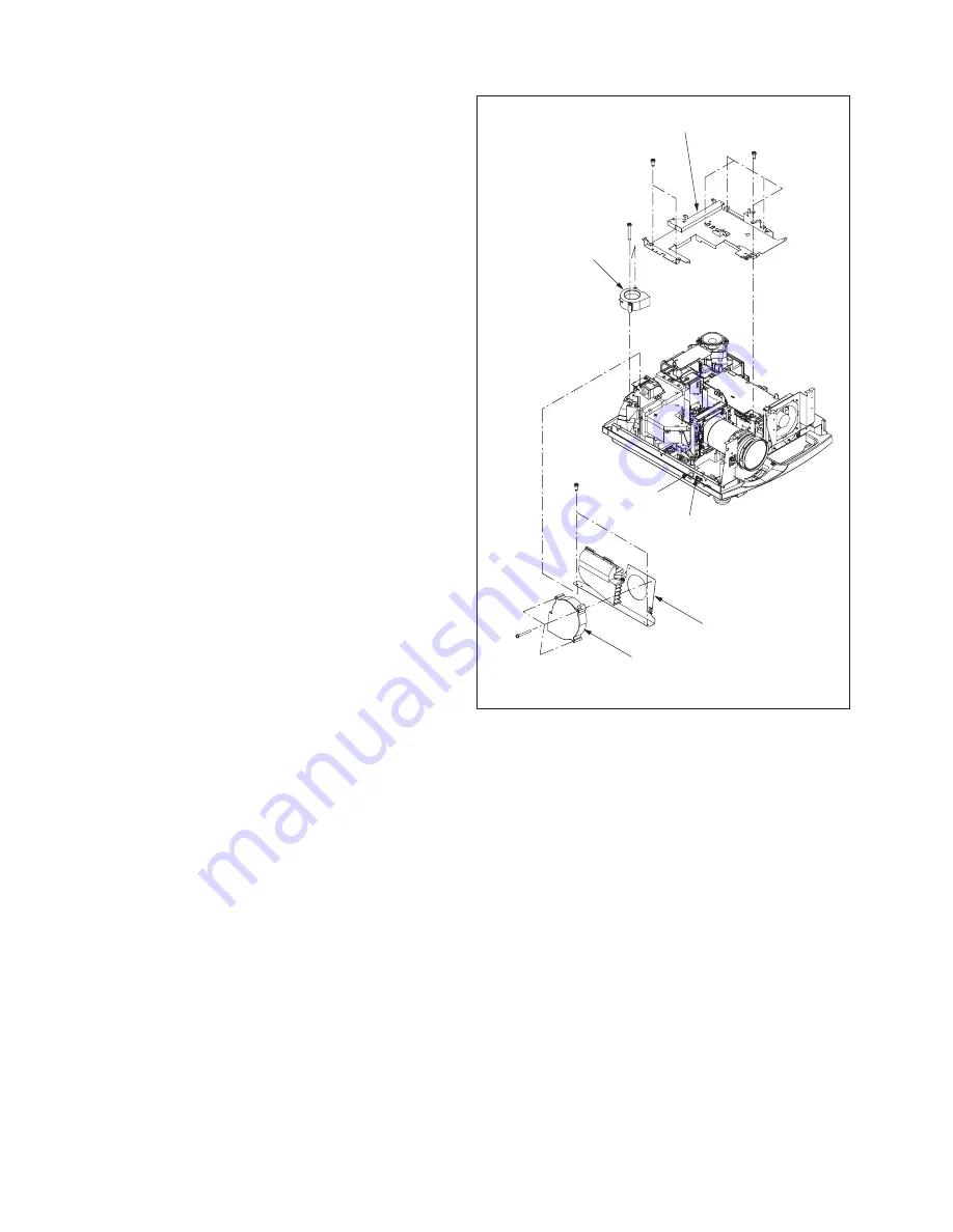
ax2
bx4
cx2
dx3
ex2
ND
NB
Drive PCB holder
PBS fan
Drive fan
Fan holder L
13. Removal of the drive fan
1. Remove the terminal cover ASSY according to “1.
Removal of the terminal cover ASSY”.
2. Remove the front case unit and top cover unit ac-
cording to “3. Removal of the lens unit and zoom fo-
cus motor”.
3. Remove the top case unit according to “4. Removal
of the top case unit and KEY PCB ASSY”.
4. Remove the terminal board unit according to “8. Re-
moval of the speaker”.
5. Remove the main barrier according to “9. Removal of
the power fan”.
6. Remove the terminal ASSY according to “11. Remov-
al of the TERMINAL PCB ASSY”.
7. Remove the DRIVE PCB ASSY according to “12. Re-
moval of the DRIVE PCB ASSY and LCD block ”.
8. Remove the two screws (a) and four screws (b) as
shown in Fig. 3-10.
9. Remove the drive PCB holder as shown in Fig. 3-10.
10. Remove the two screws (C) as shown in Fig. 3-10.
11. Disconnect the connector (ND) as shown in Fig. 3-10.
12. Remove the fan holder L as shown in Fig. 3-10.
13. Remove the three screws (d) as shown in Fig. 3-10.
14. Remove the drive fan as shown in Fig. 3-10.
14. Removal of the PBS fan
1. Remove the terminal cover ASSY according to “1.
Removal of the terminal cover ASSY”.
2. Remove the front case unit and top cover unit ac-
cording to “3. Removal of the lens unit and zoom fo-
cus motor”.
3. Remove the top case unit according to “4. Removal
of the top case unit and KEY PCB ASSY”.
4. Remove the terminal board unit according to “8. Re-
moval of the speaker”.
5. Remove the main barrier according to “9. Removal of
the power fan”.
6. Remove the terminal ASSY according to “11. Remov-
al of the TERMINAL PCB ASSY”.
7. Remove the DRIVE PCB ASSY according to “12. Re-
moval of the DRIVE PCB ASSY and LCD block ”.
8. Remove the fan holder L according to “13. Removal
of the drive fan”.
9. Remove the two screws (e) as shown in Fig. 3-10.
10. Disconnect the connector (NB) as shown in Fig. 3-10.
11. Remove the PBS fan as shown in Fig. 3-10.
Fig. 3-10
Summary of Contents for LC62 CHASSIS XL6500LU
Page 22: ... 4 PCB LOCATION Fig 1 1 2 3 4 5 6 7 8 9 10 11 12 13 14 ...
Page 108: ... MEMO ...
Page 119: ...P XL 00LU XL 00U ...
Page 123: ...P XL 00LU XL 00U ...
Page 130: ...P 12 XL 00LU XL 00U ...


