background image

27

•••••••••••••••••••••••••••••••••••••••••••••••••••••••••••••••••••••••••••••••••••••••••••••••••••••••••••••••••••••• Basic Operations

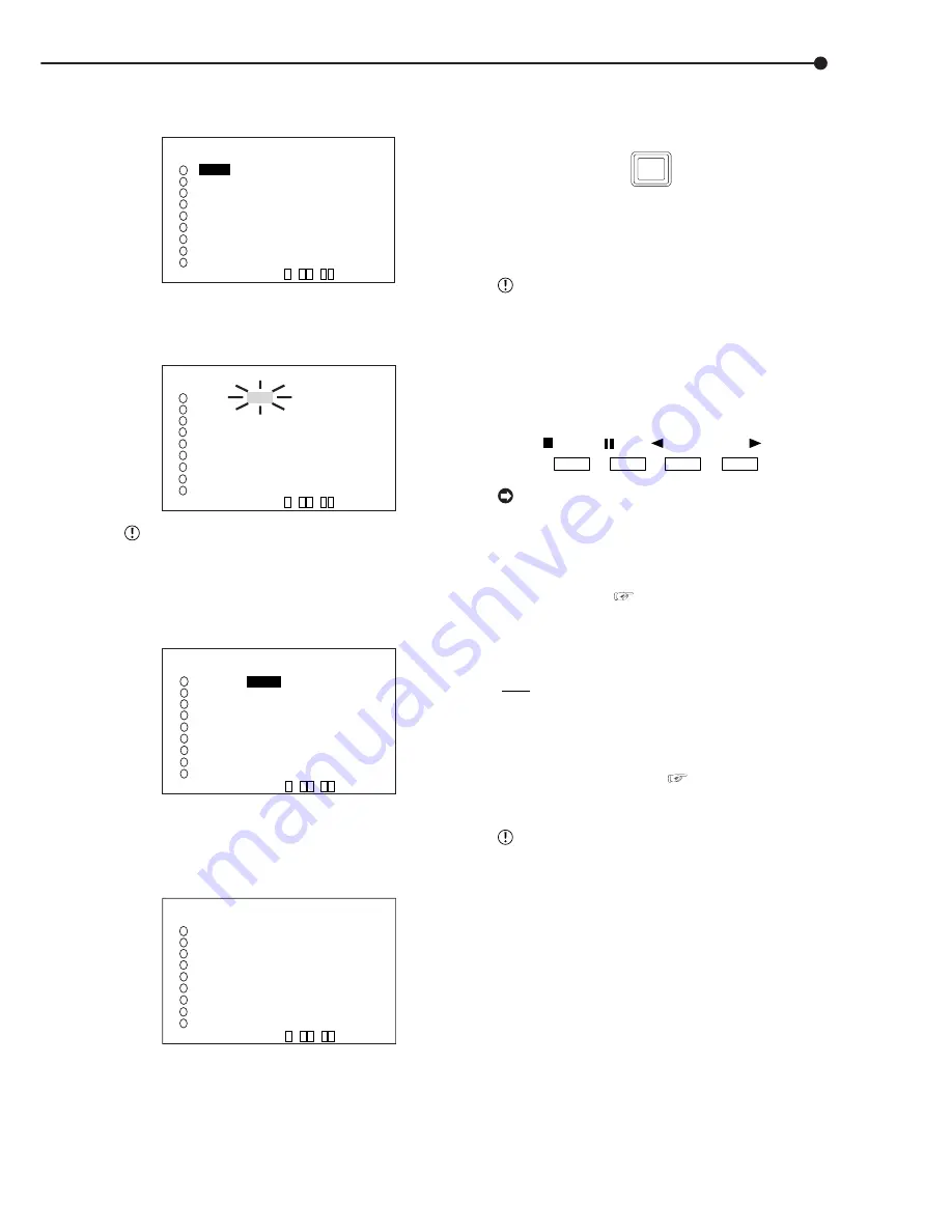
6. Turn the JOG dial to select “0.4P” and turn the SHUTTLE
ring clockwise.

• Setting is confirmed and flashing stops.

  <RECORD SETTING>   ALARM CH
 NO  PPS    GRADE A-PPS  A-GRADE
     

0.4P   

STD   3P     STD

     3P     STD   3P     STD
     3P     STD   3P     STD
     3P     STD   3P     STD
     3P     STD   3P     STD
     3P     STD   3P     STD
     3P     STD   3P     STD
     3P     STD   3P     STD
     3P     STD   3P     STD
 <ESTD REC>       D  H  M 

9

7

4
5
6

1

2

3

8

7. Turn the JOG dial clockwise to reverse display “GRADE”
and turn the SHUTTLE ring clockwise.

• The background of the “GRADE” setting turns red and
flashes.

  <RECORD SETTING>   ALARM CH
 NO  PPS    GRADE A-PPS  A-GRADE
     0.4P   STD   3P     STD
     3P     STD   3P     STD
     3P     STD   3P     STD
     3P     STD   3P     STD
     3P     STD   3P     STD
     3P     STD   3P     STD
     3P     STD   3P     STD
     3P     STD   3P     STD
     3P     STD   3P     STD
 <ESTD REC>       D  H  M 

9

7

4
5

6

1
2
3

8

 When the setting item is flashing, the menu

screen cannot be cleared even when pressing the
SET UP button.

8. Turn the JOG dial to select “HIGH” and turn the SHUTTLE
ring clockwise.

• The setting is confirmed and flashing stops.

9

7

4
5
6

1

2

3

8

  <RECORD SETTING>   ALARM CH
 NO  PPS    GRADE A-PPS  A-GRADE
     0.4P  

 HIGH

  3P     STD

     3P     STD   3P     STD
     3P     STD   3P     STD
     3P     STD   3P     STD
     3P     STD   3P     STD
     3P     STD   3P     STD
     3P     STD   3P     STD
     3P     STD   3P     STD
     3P     STD   3P     STD
 <ESTD REC>       D  H  M 

9. When the setting is complete, turn the SHUTTLE ring
counterclockwise.

• The cursor appears to the camera number on the left.
• When continuing with other camera number settings, turn
the JOG dial to move the cursor to the desired camera number
and repeat steps 4 ~ 9 to perform settings.

  <RECORD SETTING>   ALARM CH
 NO  PPS    GRADE A-PPS  A-GRADE
 >>   0.4P   HIGH  3P     STD
     3P     STD   3P     STD
     3P     STD   3P     STD
     3P     STD   3P     STD
     3P     STD   3P     STD
     3P     STD   3P     STD
     3P     STD   3P     STD
     3P     STD   3P     STD
     3P     STD   3P     STD
 <ESTD REC>       D  H  M 

9

7

4
5
6

1

2

3

8

10. Turn the SHUTTLE ring counterclockwise three times or
press the SET UP button to return to the normal screen.

11. Press the REC/STOP button.

• The REC/STOP button turns on and recording starts.

12. To stop recording, press the REC/STOP button for more
than 1 second.

• Recording stops and the REC/STOP button turns off.

REC/STOP

 Basic playback

This unit allows recorded video to be played back using
various methods. The basic playback described here is the
most common method for playback.

 This unit will stop playback when a request for

acquisition of live images is communicated during
playback.

1. Press the PLAY button ( inside the front door) on the front of
the unit.

• Recorded contents of the HDD are played back.
• After turning the power on, the oldest recorded video is
played back first. Otherwise, playback resumes at the position
of the previous playback.

STOP

PAUSE

REV. PLAY PLAY

 When the “HDD REPEAT PLAY” setting in the

“HDD SETTINGS” is set to “OFF”, playback is
stopped at the end of the recorded section or at the
end of the physical HDD is reached. When the “HDD
REPEAT PLAY” setting is set to “ON”, recorded video
data is played back repeatedly when the end of the
HDD is reached. ( 

 see “HDD REPEAT PLAY”,

page 51).

2-1. (To change HDD or Compact Flash Card playback device
• • • )

• Setting ( default : “MAIN” )
“MAIN” : Select when playing back MAIN HDD contents.

“SUB” : Select when playing back SUB HDD contents.

“CFC” : Select when playing back CFC contents.

• When changing the playback device to Compact Flash Card,
press the SEARCH button twice ( 

 see page 71) to display

the <SEARCH SELECTION> screen and select “CFC”
(Compact Flash Card) in “PLAYBACK DEVICE”.

 “SUB” appears on the screen when “PARTITION”

is selected on “HDD SETTING” of the <INITIALIZA-
TION> screen.

2-2. Press the PLAY button.

• Plays from the playback device that has been selected.

Summary of Contents for DX-TL910U

Page 1: ...1 DIGITAL RECORDER INSTALLATION AND OPERATION MANUAL MODEL DX TL910U THIS INSTRUCTION MANUAL IS IMPORTANT TO YOU PLEASE READ IT BEFORE USING YOUR DIGITAL RECORDER ...

Page 2: ...PARTS INSIDE REFER SERVICING TO QUALIFIED SERVICE PERSONNEL RISK OF ELECTRIC SHOCK DO NOT OPEN WARNING The lightning flash with arrowhead symbol within an equilateral triangle is intended to alert the user to the presence of uninsulated dangerous voltage within the product s enclosure that may be of sufficient magnitude to constitute a risk of electric shock The exclamation point within an equilat...

Page 3: ...t qui peuvent être suffisamment importantes pour conduire au risque d électrocution Le point d exclamation au sein d un triangle équilateral a pour objet de tirer l attention de l utilisateur sur le fait qu il y a des instructions de mise en service et d entretien de réparation dans les fiches descriptives de l appareil qui doivent obligatoirement être respectées AVERTISSEMENT AFIN D ÉVITER TOUT R...

Page 4: ...to ensure reliable operation of the product and to protect it from overheating and these openings must not be blocked or covered This prod uct should never be placed near or over a radiator or heat register This product should not be placed in a built in installation such as a bookcase or rack un less proper ventilation is provided or the manufac turer s instructions have been adhered to 10 Power ...

Page 5: ...ics as the original part Unauthorized substitutions may result in fire electric shock or other hazards 19 Safety Check Upon completion of any service or repairs to this product ask the service technician to perform safety checks to determine that the product is in safe oper ating conditions 20 Heat The product should be situated away from heat sources such as radiators heat registers stoves or oth...

Page 6: ...E Never use petroleum based cleaners Clean with a soft cloth moistened with soap and water and wipe dry PVC cables or leads should not be left in contact with the cabinet surface for long periods INSTALLATION LOCATION For excellent performance and lasting reliability install in a location that is 1 Well ventilated out of direct sunlight and away from direct heat 2 A solid vibration free surface 3 ...

Page 7: ...ot be taken as a guaranteed lifespan of the products Use the ELAPSED TIME on the INFORMATION SERVICE screen as a guide to performing checkups There may be cases when the unit s built in MOTION DETECTION function does not operate properly due to external condition or video input signal or other factors The user will not be indemnified for problems e g recording failure or playback failure that occu...

Page 8: ... Various record setting Recording interval and picture quality of each camera can be set individually to both normal recording and alarm recording see pages 45 47 Flexible alarm recording Any camera number for alarm recording of 2 modes such as Alarm Channel Alarm Plus can be assigned 4 triggers are also selectable out of various combination such as external alarm input and motion detection extern...

Page 9: ...terval and picture grade for all channels and other menu settings are set to the default see pages 21 22 Microsoft is either registered trademarks or trademarks of Microsoft Corporation in the United States and or other countries Compact FlashTM is a trademark of SanDisk Corporation Storage capacity is indicated in gigabytes GB 1GB 1000 x 1000 x 1000 bytes ...

Page 10: ...f the SPLIT SEQUENCE button ZOOM button and camera number buttons 40 MPX DISPLAY SETTINGS 41 SPLIT4 SCREEN SETTING 41 SPLIT9 SCREEN SETTING 41 42 SEQUENCE SETTING 42 INTERLACE 42 MOTION DETECTION SETTINGS 43 44 SELECTION CAMERA NUMBER 43 DETECTION MASK SETTING 43 SENSITIVITY 44 MOTION THRESHOLD 44 TEST MODE 44 RECORD SETTINGS 45 47 Settings concerning normal recording and alarm recording 45 Record...

Page 11: ...rowser 81 86 The personal computer product requirements 81 Connections 81 AUTHENTICATION 81 82 Welcome 82 86 Live monitor 82 83 Playback 83 84 Time Search 84 Alarm Search 84 Index Search 84 User maintenance 84 85 Log out 85 Change log in user 85 86 Recording time table 87 88 Continuous recording time table 87 88 HDD continuous recording time for 250GB drive 87 Without Audio recording 87 With Audio...

Page 12: ...nnecting to CCTV camera monitor sensor page 19 Connection to the alarm recording See Alarm Recording Connection page 20 and Rear View pages 17 18 The unit is booted AUTO SET UP Setting the auto set up See AUTO SET UP pages 21 22 Only when the unit is turned on for the first time the AUTO SET UP screen is displayed automatically It is not automatically displayed after next time Selecting the NO in ...

Page 13: ... Changing the sequence setting See SEQUENCE SETTING page 42 Setting other various functions Changing the display mode See CLOCK LOCATION SETTING page 36 and DUPLEX MODE DISPLAY page 38 Setting the camera title memo See CAMERA TITLE MEMO SETTING pages 36 37 and CAMERA DISPLAY page 36 Setting to output signals of the unit status See MODE OUT 1 MODE OUT 5 page 53 Setting the buzzer See BUZZER pages 5...

Page 14: ...d search functions adjusting the playback speed and rewinding or for warding the recording images 7 JOG dial Used to set various menus and search functions forwarding or rewinding the image during playback field by field 8 SPLIT SEQUENCE button Press the button to display SPLIT9 SPLIT4 screen or SEQUENCE screen setting on multiplexer functions 9 ZOOM button Pressing this button twice three and fou...

Page 15: ...mpact Flash Card Inserting Card 1 Remove the COMPACT FLASH slot cover attached to the unit 2 Please turn down the side which contains notch in right and left securely insert the Card until the CFC EJECT button pops out Do not eject the Card when copying restoring copy ing loading menus or immediately after inserting the Card The Card or the contained data may become damaged Securely insert the Com...

Page 16: ... again the unit resumes playback and the button turns off When pressing this button during shuttle playback the set playback speed is maintained even when letting go of the SHUTTLE ring SHUTTLE HOLD Pressing while playback is stopped will playback the end of latest recorded portion as a still image REV PLAY REVERSE PLAY button Pressing this button the unit switches to reverse play back and the but...

Page 17: ...n this terminal receives the CLOCK ADJ signal INFORMATION The on screen clock can be reset to the nearest hour by applying a signal to the CLOCK ADJ terminal For example if the current time is 11 29 59 it will be reset to 11 00 00 and if the current time is 11 30 00 it will be reset to 12 00 00 1 MAIN switch This is the main power switch When using this unit set this switch to ON Otherwise the pow...

Page 18: ...in the REAR TERMINAL SETTINGS menu CALL OUT terminal CALL OUT GND terminals This is the ISOLATION output terminal Information that can be transmitted externally consists of CALL OUT settings made on the REAR TERMINAL SET TINGS menu screen as well as fixed output set tings DC 12V OUT terminal Will only output when the MAIN switch is ON The maximum electric current is 350mA 12 RS 232C connector This...

Page 19: ... 32 ø0 65 mm AWG 28 22 Cut the designated area from the electric wire s outer covering vinyl portion 5 7mm To GND terminal To ALARM IN terminal corresponds to the CAMERA SENSOR 1 To MIC jack MICROPHONE CAUTION Connecting a coaxial transmission camera wrong may damage the input terminal Be careful CAUTION When a microphone is connected to the MIC jack the MIC jack will be given priority over the AU...

Page 20: ...log video recorder This unit is equipped with video output RCA and audio output RCA connectors on the front and OUTPUT A S Y C OUTPUTA VIDEO BNC andAUDIO OUT RCA con nectors on the rear Video signals can be simultaneously outputted from the video output connector on the front and the OUTPUT A VIDEO S Y C connector on the rear In the same manner audio signals can be outputted in simul taneously fro...

Page 21: ...ot want to execute AUTO SET UP Select NO by turning the JOG dial and turn the SHUTTLE ring clockwise SETTING UP is displayed on the screen and the unit starts up 4 2 When execute AUTO SET UP Select YES by turning the JOG dial and turn the SHUTTLE ring clockwise The CAMERA CHECK screen appears The cameras connected and the video condition can be confirmed in this screen CAMERA CHECK EXECUTE CHECK C...

Page 22: ...mera number button 1 and press the POWER button when the MAIN switch is set to ON and the POWER button is set to OFF The CAMERACHECK screen appears However all menu of record setting will be reset INITIALIZATION Please perform initialization when a INITIALIZATION setup is changed INITIALIZATION HDD SETTING NORMAL POWER OFF INITIALIZATION ALL DATA WILL BE ERASED WHEN PROCEED INITIALIZATION 1 Turn O...

Page 23: ...NGS Use the JOG to move up down across and to make a change and use the SHUTTLE to select and accept a change and to go to the next or previous menu SHUTTLE ring JOG dial Example Set DISPLAY MODE to 3 default 1 1 Set the MAIN switch on the rear of the unit to ON Press the POWER button on the front after the ACCESS indicator turns off SETTING UP appears on the screen and the unit is booted POWER bu...

Page 24: ...utton to display the SETTINGS screen 2 Check to see that the cursor is positioned at TIME DATE DISPLAY SETTINGS and then turn the SHUTTLE ring clockwise The TIME DATE DISPLAY SETTINGS screen appears 3 Check to see that the cursor is positioned at TIME DATE ADJUST and then turn the SHUTTLE ring clockwise The TIME DATE ADJUST screen appears TIME DATE ADJUST DAYLIGHT SAVING OFF MONTH 01 DAY 01 YEAR 2...

Page 25: ...llowed display range is 99 years between 1 1 2001 31 12 2099 The unit is also equipped with a function to automatically calculate leap years The date returns to the year 2001 after 31 12 2099 Recorded capacity display function 01 01 2004 THU 00 00 00 15P 99 A00001 Year Month Day Day of the week Alarm recording number Minute Second Hour Playback interval Single screen playback only Recorded capacit...

Page 26: ...P and GRADE to HIGH for normal recording 1 Press the SET UP button to display the SETTINGS screen 2 Turn the JOG dial to move the cursor to RECORD SETTINGS and turn the SHUTTLE ring clockwise The RECORD SETTINGS screen appears RECORD SETTINGS ALARM SETTING RECORD SETTING ALARM REC DURATION 5S PRE ALARM REC S S MOTION DET REC ALARM 3 Turn the JOG dial to move the cursor to RECORD SETTING and then t...

Page 27: ... REC D H M 9 7 4 5 6 1 2 3 8 10 Turn the SHUTTLE ring counterclockwise three times or press the SET UP button to return to the normal screen 11 Press the REC STOP button The REC STOP button turns on and recording starts 12 To stop recording press the REC STOP button for more than 1 second Recording stops and the REC STOP button turns off REC STOP Basic playback This unit allows recorded video to b...

Page 28: ...n the SHUTTLE ring clockwise Setting is confirmed and flashing stops 4 Turn the JOG dial to reverse display DAY and turn the SHUTTLE ring clockwise The background of the setting item changes to red and flashes 5 Turn the JOG dial to display 03 for DAY and turn the SHUTTLE ring clockwise Setting is confirmed and flashing stops 6 Repeat steps 4 and 5 to set YEAR HOUR MINUTE and SECOND TIME DATE SEAR...

Page 29: ...ull screen view by selecting a cam era number from the SPLIT9 screen of the search result when ALL is selected in the SELECTION CAMERA NUMBER setting press the SEARCH button to clear the SEARCH menu and press the desired camera number button The desired video is displayed in full screen Press the camera number buttons during still image playback to call up search mode The search mode status may co...

Page 30: ...ETTINGS OUTPUT A OUTPUT B ON OFF OFF OUTPUT B OUTPUT A SPLIT4 SCREEN SETTING SPLIT9 SCREEN SETTING SEQUENCE SETTING INTERLACE ON SUB MENU 1 MAIN MENU SUB MENU 2 SUB MENU 3 SET UP SPLIT9 SCREEN SETTING SPLIT9 SPLIT4 SCREEN SETTING SPLIT4 a SPLIT4 b SPLIT4 c CHARACTERS 0123456789 ABCDEFGHIJKLMNOPQRSTUVWXYZ abcde f gh i j k l mnopqrs t uvwxyz SHUTTLE BACK CAMERA TITLE MEMO SETTING MEMO SHUTTLE CHARAC...

Page 31: ...DE A ALARM SETTING RECORD SETTING PRE ALARM REC S S MOTION DET REC ALARM TIMER PROGRAM P1 DW START END MODE MD 1 2 3 4 5 6 7 8 SPL SAT SUN RECORD SETTING ALARM CH NO PPS GRADE A PPS A GRADE 3P STD 3P STD 3P STD 3P STD 3P STD 3P STD 3P STD 3P STD 3P STD 3P STD 3P STD 3P STD 3P STD 3P STD 3P STD 3P STD 3P STD 3P STD ESTD REC D H M SET UP ALARM SETTING A ALARM CH ALARM RECORD CAMERA TRIGGER 1 EXT 2 E...

Page 32: ...K SETTINGS MEMO SUB MENU 1 MAIN MENU SUB MENU 2 SUB MENU 3 RS 232C SETTINGS TRANSMISSION MODE 9600 DATA BIT LENGTH 8BIT PARITY BIT NONE STOP BIT LENGTH 1BIT DELIMITER CR LAN IP ADDRESS 192 168 000 100 SUB NET MASK 255 255 255 000 GATEWAY 000 000 000 000 E MAIL ADDRESS SERVICE PORT SETTING ALARM NOTIFICATION SETTING MAC ADDRESS 08 00 70 2E 3F FF PLEASE PRESS SET UP BUTTON TO APPLY NEW SETTING ALARM...

Page 33: ...L HDD MASTER HDD 250GB SLAVE NONE MAIN START 01 01 2004 00 00 00 END 01 01 2004 00 00 05 SUB START 01 01 2004 00 00 00 END 01 01 2004 00 00 05 CFC INFORMATION CFC CAPACITY 128MB START END SUB MENU 3 RESET TO FACTORY SETTINGS EXECUTE SHUTTLE EXECUTE CANCEL WARNING LOG LIST NO DATE TIME WARNING 0001 01 01 04 00 00 00 ALM ON 1 1 SET UP 1 QUICK SETTINGS LOAD SETTING DATA FROM CFC SAVE SETTING DATA TO ...

Page 34: ...TION DETECTION SETTINGS RECORD SETTINGS TIMER PROGRAM SETTINGS INITIAL SET UP INFORMATION QUICK SETTINGS MEMO INFORMATION SERVICE 1 2 HDD INFORMATION CFC INFORMATION WARNING LOG LIST RESET TO FACTORY SETTINGS MAIN HDD DATA CLEAR SUB HDD DATA CLEAR CFC DATA CLEAR INFORMATION SERVICE 2 2 ELAPSED TIME SYSTEM 3H HDD SETTING PARTITION PARTITION SIZE 10 1 1 1 1 SET UP PASSWORD SETTING FIRST SECOND 1 2 3...

Page 35: ... MAIN MAIN START END SUB MENU 1 SEARCH SELECTION SEARCH TYPE ALARM LIST SELECTION CAMERA NUMBER ALL DATE TIME PLAYBACK DEVICE SUB SUB START 01 01 2004 00 00 00 END 01 01 2004 00 00 05 COPY DIRECTION MAIN HDD CFC MODE OVERWRITE TRANSFER PERIOD START END START 01 01 2004 00 00 00 END 01 01 2004 00 00 10 EXECUTE RESTORE DIRECTION CFC MAIN HDD MODE OVERWRITE TRANSFER PERIOD START END START 01 01 2004 ...

Page 36: ... the and buttons to move the time and date to the desired display position and turn the SHUTTLE ring clockwise The setting is confirmed The date the present time etc on a screen can be moved to right and left and the upper and lower sides by pushing and button The display can be moved continuously to the right by turning the JOG dial clockwise to the left by turning it counterclockwise 3 Turn the ...

Page 37: ...G dial can be turned to continuously move the cursor horizontally 5 Turn the JOG dial clockwise to reverse display the character on the right 6 Repeat steps 3 5 to input ENTRANCE in the string To erase an inputted character move the cursor to the very left character _ space turn the SHUTTLE ring clockwise and confirm To change a character inputted in error 1 While one of the characters in the stri...

Page 38: ... MEMO SETTING DUPLEX MODE DISPLAY BOTTOM MODE 1 01 01 2004 00 00 00 Setting default BOTTOM BOTTOM The operation condition is displayed on the bottom of the screen NONE The operation condition is not displayed TOP The operation condition is displayed on the top of the screen 1 Press the SET UP button SETTINGS Select DUPLEX MODE DISPLAY in the TIME DATE DISPLAY SETTINGS screen Display the desired se...

Page 39: ...quential display previous to cancelling When a menu screen is displayed the single screen display will not appear even when pressing a camera number button 1 9 In this case clear the menu screen and then press a camera number but ton 1 9 ZOOM button operations By pressing the ZOOM button in single screen display the displayed video can be viewed at 100 200 or 400 magnification If the OUTPUT B indi...

Page 40: ...elected in OUTPUT A OUTPUT B SPLIT9 SCREEN SETTING screen is displayed using SPLIT9 display During video display the corresponding camera number button lights The video of camera number selected in OUTPUT A OUTPUT B SPLIT4 SCREEN SETTING screen is displayed using SPLIT4 display During video display the corresponding camera number button lights The single screen video set in OUTPUT A OUTPUT B SEQUE...

Page 41: ...and turn the SHUTTLE ring clockwise The most upper left camera number reverses in color 4 Turn the JOG dial to move to the camera number with the reversed display and turn the SHUTTLE ring clockwise The background of the camera number turns red and flashes 5 Turn the JOG dial to display the camera number to set and turn the SHUTTLE ring clockwise Flashing stops The same camera number can be set mu...

Page 42: ...ound of the TIME setting turns red and flashes 6 Display the desired time and turn the SHUTTLE ring clockwise The setting is confirmed and flashing stops The time can be set at 1 second intervals max 30 seconds 7 Turn the SHUTTLE ring counterclockwise The cursor appears to sequence number on the left 8 Repeat steps 3 7 to set other display orders of camera number and time 9 When setting switching ...

Page 43: ... set SELECTION CAMERA NUMBER The camera for motion detection setting is selected Since settings can be made for each camera more detailed set tings are possible 1 MOTION DETECTION SETTINGS SELECTION CAMERA NUMBER DETECTION MASK SETTING SENSITIVITY HIGH LOW MOTION THRESHOLD 5 TEST MODE Setting default 1 1 2 3 4 5 6 7 8 9 When selecting the MOTION DETECTION SETTINGS screen during single screen displ...

Page 44: ...5 TEST MODE Setting default HIGH LOW HIGH LOW HIGH LOW HIGH LOW HIGH LOW HIGH LOW Sensitivity increases as increases from HIGH LOW to HIGH LOW To detect the slightest changes set to HIGH LOW However detection may not operate properly due to flickering of fluorescent lighting etc 1 Select the camera to set the sensitivity in SELECTION CAMERA NUMBER see page 43 2 Display the desired setting in SENSI...

Page 45: ...lashes Setting default ALARM CH ALARM CH Alarm recording is performed for only the cameras set for alarm recording and inputted with alarm signals When there is input of alarm signals from multiple cameras alarm recording is performed for all cameras containing alarm signals ALARM PLUS Recording is performed in the frame speed set in A PPS for the camera inputted with alarm signals during normal r...

Page 46: ... 0 2P 0 1P 0 05P 0 025P Recording cannot be performed with camera set to this item Pressing the WARNING RESET button while the cursor is on the left of the desired camera number changes that camera s PPS and A PPS to For details concerning normal recording settings see Setting the recording interval and recording picture quality for normal recording pages 26 27 14 Display the desired item to set a...

Page 47: ... time longer than the maximum the set tings will turn red Set the time within the recording time limit so that the display returns to white Even if the time is set beyond the limit Pre Alarm record ing time is not changed 1 Press the SET UP button SETTINGS Select PRE ALARM REC in the RECORD SETTINGS screen and display the desired setting 2 Turn the SHUTTLE ring counterclockwise or press the SET UP...

Page 48: ...nd end day of the week are set When selecting SPL in DW the period from the start day of the week and end day of the week set here are active Example Using program 1 in TIMER PROGRAM P2 REC MODE A will record to Wednesday Saturday from 12 30 to 13 00 and MD is set to ON 1 Press the SET UP button SETTINGS select TIMER PROGRAM SETTINGS TIMER PROGRAM SETTINGS SELECTED PATTERN P1 SET HOLIDAY SETTING R...

Page 49: ... DW START END MODE MD 1 SPL 12 30 13 00 A ON 2 3 4 5 6 7 8 SPL WED SAT 21 Turn the SHUTTLE ring counterclockwise or press the SET UP button Turn the SHUTTLE ring counterclockwise to return the cursor to the previous operation Then press the SET UP button to clear the TIMER PROGRAM SETTINGS screen and return to the normal screen If there is an unset item with in the program display the setting scre...

Page 50: ...DD set in PARTITION is displayed with the percentage and the record able time of that storage area is displayed in ESTD REC For details on PARTITION see page 79 MOTION DET REC Recording is done with the recording interval and the quality set by A PPS and A GRADE independent of whether ALARM or NORMAL has been selected for details concerning setting MOTION DET REC see page 47 ALARM REC DURATION The...

Page 51: ...on check using playback or playback with changed play back intervals HDD SETTINGS HDD REPEAT REC MAIN HDD REPEAT REC SUB The operation when HDD Hard Disk Drive space be comes full during recording HDD SETTINGS HDD REPEAT REC MAIN ON HDD REPEAT REC SUB OFF HDD REPEAT PLAY OFF IM CHECK PLAY OFF SEQUENTIAL PLAY OFF HDD REPEAT REC SUB appears when PARTI TION is selected on HDD SETTING of the INITIALI ...

Page 52: ...y select NONE in the CAMERA DISPLAY see page 36 AUDIO RECORDING This unit can simultaneously record audio along with the video When recording audio the continuous recording time becomes shorter than when recording only video INITIAL SET UP INFORMATION HDD SETTINGS AUDIO RECORDING OFF REAR TERMINAL SETTINGS COMMUNICATION PORT SETTINGS INFORMATION SERVICE PASSWORD LANGUAGE SELECTION Setting default ...

Page 53: ...E OUT 1 MODE OUT 5 to output signals and then confirm 3 To set other terminals repeat step 2 4 Turn the SHUTTLE ring counterclockwise or press the SET UP button KEY SOUND It is possible for the unit to make button sounds when using the operation buttons on the front of the unit or when operating the JOG dial or SHUTTLE ring REAR TERMINAL SETTINGS MODE OUT 1 OFF MODE OUT 2 OFF MODE OUT 3 OFF MODE O...

Page 54: ... WARNING ALARM OFF SETTING BUZZER When reaching the remaining capacity set in REMAIN HDD When a failure occurs and a warning is displayed When an alarm recording or emergency recording is started REMAIN ON OFF OFF WARNING OFF ON OFF ALARM OFF OFF ON OFF OFF OFF OFF 1 Press the SET UP button SETTINGS INITIAL SET UP INFORMATION Select BUZZER in the REAR TERMINAL SETTINGS screen Display the desired s...

Page 55: ...EMERGENCY REC DURATION 10M For details concerning setting EMERGENCY RE CORDINGS see page 68 Setting default 10M 1M 2M 5M 10M 20M 30M 60M 1 Press the SET UP button SETTINGS INITIAL SET UP INFORMATION Select EMERGENCY REC DURATION in the REAR TERMINAL SETTINGS screen Display the desired setting and confirm 2 Turn the SHUTTLE ring counterclockwise or press the SET UP button COMMUNICATION PORT SETTING...

Page 56: ...T UP button SETTINGS INITIAL SET UP INFORMATION Select LAN in the COMMUNICATION PORT SETTINGS screen and turn the SHUTTLE ring clockwise The LAN screen appears LAN IP ADDRESS 192 168 000 100 SUB NET MASK 255 255 255 000 GATEWAY 000 000 000 000 E MAIL ADDRESS SERVICE PORT SETTING ALARM NOTIFICATION SETTING MAC ADDRESS 08 00 70 2E 3F FF PLEASE PRESS SET UP BUTTON TO APPLY NEW SETTING 2 Select the se...

Page 57: ...ET UP INFORMATION COMMUNICATION PORT SETTING select ALARM NOTIFICATION SETTING in the LAN screen The ALARM NOTIFICATION SETTING screen appears ALARM NOTIFICATION SETTING NO IP ADDRESS TARGET OWN 1 000 000 000 000 55111 01111 2 000 000 000 000 55111 01112 3 000 000 000 000 55111 01113 4 000 000 000 000 55111 01114 5 000 000 000 000 55111 01115 WARNING OFF ALARM SENS OFF REC MODE OFF RETRY TIME 10S ...

Page 58: ...PARTITION SIZE appears on page 2 2 of the IN FORMATION SERVICE screen when PARTITION is selected on HDD SETTING of the INITIALIZA TION screen HDD INFORMATION CFC INFORMATION INFORMATION is used to check the amount of available space in the HDD and Compact Flash Cards inserted into the unit 1 1 To check HDD RECORD data Press the SET UP button SETTINGS INITIAL SET UP INFORMATION Select HDD INFORMATI...

Page 59: ...fter power is restored For power outages that occur while timer recording is standing by P LOSS that indicates a power outage is not displayed In addition power outages that overlap with timer recording start times and those where power is restored after the recording end time are also not recorded 2 Turn the SHUTTLE ring counterclockwise or press the SET UP button RESET TO FACTORY SETTINGS Menu s...

Page 60: ...A CLEAR and SUB HDD DATA CLEAR About PASSWORD LOCK for OPERATION CON TROL level 1 to level 3 1 Input the PASSWORD of level 1 to level 3 2 Set the PASSWORD LOCK The PASSWORD LOCK of level 1 will be active When The PASSWORD LOCK of level 1 is active functions of all operations can be locked 3 Unlock the PASSWORD LOCK of level 1 The PASSWORD LOCK of level 2 will be active When The PASSWORD LOCK of le...

Page 61: ...en To unlock the PASSWORD 1 To unlock the PASSWORD for level 1 and level 2 Press the LOCK button The UNLOCK PASSWORD screen appears UNLOCK PASSWORD 1 2 EXECUTE SHUTTLE TO SET PASSWORD 2 Confirm the cursor is moved to the left side of level 1 and turn the SHUTTLE ring clockwise The first digit reverse in color 3 Input 4 digits of the PASSWORD by pressing the camera number buttons or the ZOOM button...

Page 62: ... appear PASSWORD SETTING FIRST SECOND 1 2 3 PRESS WARNING RESET BUTTON TO CLEAR PASSWORD SHUTTLE TO SET PASSWORD 2 2 Input the new PASSWORD referring to To register the PASSWORD 3 1 To change the PASSWORD for level 4 Display the PASSWORD screen Turn the JOG dial to move the cursor to cursor to HDD DATA CLEAR and turn SHUTTLE ring clockwise The CHANGE PASSWORD screen appears 3 2 Input the 4 digits ...

Page 63: ... one item of IP ADDRESS SUB NET MASK GATEWAY SERVICE PORT SETTING on the LAN screen or IP ADDRESS TARGET or OWN of the ALARM NOTIFICATION SETTING settings are read out or when settings are changed restart is performed auto matically After menu reset has been completed the time is not correct and the correct time should be set 5 Finalizing updated menu settings Turn the SHUTTLE ring counterclockwis...

Page 64: ...C MAIN ON HDD REPEAT REC SUB OFF HDD REPEAT PLAY OFF IM CHECK PLAY OFF 4 TIMER PROGRAM SETTINGS screen setting see pages 48 50 SELECTED PATTERN P1 TIMER PROGRAM SETTINGS SELECTED PATTERN P1 SET HOLIDAY SETTING REC MODE A REC MODE B REC MODE C REC MODE D ALARM REC DURATION 5S 5 RECORD SETTING A screen setting see page 50 All cameras 1 9 PPS GRADE Set desired interval and picture quality for each ca...

Page 65: ... AUDIO RECORDING OFF see page 52 INITIAL SET UP INFORMATION HDD SETTINGS AUDIO RECORDING OFF REAR TERMINAL SETTINGS 3 HDD SETTINGS screen setting see pages 51 52 HDD REPEAT REC MAIN ON HDD SETTINGS HDD REPEAT REC MAIN ON HDD REPEAT REC SUB OFF HDD REPEAT PLAY OFF IM CHECK PLAY OFF 4 TIMER PROGRAM SETTINGS screen setting see pages 48 50 SELECTED PATTERN P2 HOLIDAY SETTING 31 12 01 01 02 01 03 01 TI...

Page 66: ...5 00 20 00 B OFF PROGRAM NO 3 SAT 08 00 17 00 B OFF PROGRAM NO 4 SUN 08 00 17 00 B OFF PROGRAM NO 5 HOL 08 00 17 00 B OFF SPL MON FRI TIMER PROGRAM P2 DW START END MODE MD 1 SPL 08 00 15 00 A OFF 2 SPL 15 00 20 00 B OFF 3 SAT 08 00 17 00 B OFF 4 SUN 08 00 17 00 B OFF 5 HOL 08 00 17 00 B OFF 6 7 8 SPL MON FRI When completed with all settings above and after clear ing the menu screen press the TIMER...

Page 67: ...ING D screen setting see page 50 Camera number 1 2 3 7 8 and 9 only TRIGGER MD EXT ALARM SETTING D 9 7 4 5 6 1 2 3 8 9 7 4 5 6 1 2 3 8 ALARM SETTING D ALARM CH ALARM RECORD CAMERA TRIGGER 1 MD EXT 2 MD EXT 3 MD EXT 4 EXT 5 EXT 6 EXT 7 MD EXT 8 MD EXT 9 MD EXT EMR 10 RECORD SETTING D screen setting see page 50 Camera number 1 2 3 7 8 and 9 only PPS GRADE A PPS A GRADE Set desired interval and pictu...

Page 68: ...MERGENCY RECORDING will start automatically overriding all other settings Emergency recording cannot be made when the MAIN switch is OFF the POWER button is OFF and during timer recording stand by For details concerning emergency recording set tings see page 55 Emergency recording 1 Emergency recording is performed using all cameras set to recording interval in A PPS in the RECORD SET TING screen ...

Page 69: ... even when letting go of the SHUTTLE ring during shuttle viewing 1 Press the PAUSE SHUTTLE HOLD button while holding the SHUTTLE ring in angle during shuttle playback 2 Let go of the SHUTTLE ring The playback speed is maintained To cancel shuttle hold press the PAUSE button The unit will switch to still frame playback Frame by frame playback 1 Turn the JOG dial during still frame playback Clockwis...

Page 70: ...emain un changed even when returning the playback interval to the original value To check the original playback interval of the recording pause playback and then play the video again Altering the playback interval settings and then performing a quick playback of data with long re cording time may cause discrepancies between ac tual recording time and the recording time displayed on the screen When...

Page 71: ...n SELECTION CAMERA NUMBER The camera number to search is selected SELECTION CAMERA NUMBER setting will not appear if SEARCH TYPE is set to INDEX SEARCH SEARCH SELECTION SEARCH TYPE TIME DATE SELECTION CAMERA NUMBER ALL PLAYBACK DEVICE MAIN MAIN START 02 02 2004 00 00 00 END 04 04 2004 12 30 15 Setting default ALL ALL 1 2 3 4 5 6 7 8 9 ALL Searches all camera numbers 1 9 and displays all images on ...

Page 72: ...desired search screen is not displayed on the screen Change the previous SEARCH TYPE setting and display the INDEX SEARCH screen or ALARM INDEX SEARCH screen When searching index signals of normal recording display the INDEX SEARCH screen When searching index signals of alarm recording or emergency recording display the ALARM INDEX SEARCH screen After performing INDEX SEARCH ALARM INDEX SEARCH SPL...

Page 73: ...en 3 Select EXECUTE FORWARD or EXECUTE REVERSE and confirm EXECUTE FORWARD Search is performed in the forward direction EXECUTE REVERSE Search is performed in the reverse direction To cancel the search press the SEARCH button twice Playback of search result from skip search will be in SPLIT9 display regardless of whether the SELECTION CAMERA NUMBER see page 71 is set to ALL or individual camera nu...

Page 74: ... list ALARM LIST SEARCH 00004 01 01 2004 00 00 04 1 00003 01 01 2004 00 00 03 EMR 00002 01 01 2004 00 00 02 1 00001 01 01 2004 00 00 01 EMR PUSH SEARCH KEY 1 2 Recorded camera Camera of alarm input Camera of alarm input displays the camera number which is input alarm signals and record camera displays the camera number which started recording When the correspondent cameras for alarm sig nals are n...

Page 75: ...ding starting ending point of the device media selected by PLAYBACK DEVICE in TIMER DATE SEARCH INDEX SEARCH and ALARM INDEX SEARCH for playback 1 Press the SEARCH button The search screen selected in previous SEARCH TYPE appears 2 1 To play back the oldest recording Select START and turn the SHUTTLE ring clockwise 2 2 To play back the last recording Select END and turn the SHUTTLE ring clockwise ...

Page 76: ...RWRITE Overwrites current data NO OVERWRITE Writes following last entry When DIRECTION and OVERWRITE on MODE all data on the Compact Flash Card re gardless of menu division is overwritten 4 Display the desired setting in TRANSFER PERIOD and confirm Setting default START END START END Sets the recording start end date time START Sets the recording start date time LATEST DATA Starts copying from the...

Page 77: ...gue video cassette recorder Prepare the unit for recording First set the input source to the external input connecting this unit 2 This unit Press the SPLIT SEQUENCE button to select the screen type to play back see page 40 Single screen SPLIT4 a b and c screen and SPLIT9 screen can be selected It is also possible to copy the video of each cam era in order using single screen sequential play back ...

Page 78: ... in the WARNING LOG LIST see pages 58 59 and are displayed in red on the screen For power outages that occur while timer recording is standing by P LOSS that indicates a power outage is not displayed In addition power outages that overlap with timer recording start times and those where power is restored after the recording end time are also not recorded RESET button When pressing the RESET button...

Page 79: ...be performed in some cases PARTITION PARTITION SIZE PARTITION mode only uses the internal HDD PARTITION mode designates the area inside the HDD that is specified as each HDD s sub device capacity for Alarm recording This independent partition inside the HDD allows to keep the data of alarm recording The normal recording area is referred to as MAIN and the alarm recording area PARTITION area is re ...

Page 80: ...ing clockwise The background of the setting turns red and flashes 3 Turn the JOG dial to select OFF and turn the SHUTTLE ring clockwise The setting is confirmed and flashing stops The set camera number screen will turn black 4 When continuing with setting for other camera number repeat steps 2 and 3 5 When completed with all settings turn the SHUTTLE ring counterclockwise or press the SET UP butto...

Page 81: ...x 768 pixels or higher The product requirement described above can not guarantee operations in all environments Lack of compatibility between Web functions and the PC peripheral driver may in rare instances re sult in abnormal operation If this happens upgrade to the newest version of Internet Explorer and try again Connections When making a direct connection between this equip ment and a personal...

Page 82: ...ed and displayed user maintenance with which the settings for user authori zation will be configured log out for ending a job or change log in user for making a change in the logged in user Depending on what the user s authorization is there are certain menus that cannot be selected During playback or during a search this device will stop playback or search mode when a request for the acquisition ...

Page 83: ...t obstacles to PC operation as determined by the performance of the PC you are using Please set it to the appropriate rate to the image retrieval speed of your machine Depending on the network capacity and the load conditions the transfer rate may not rise Only a user who has the authorization for Change Password can store screen layouts in the Recorder side using Save Layout If the user who has a...

Page 84: ...e Search Select the date and time and click Search Alarm Search Click Alarm List and the Alarm List Search MAIN screen will appear in the sub screen Select the Alarm No desired and then click Search Click Refresh to re acquire the Alarm List and click Close to hide the Alarm List Search MAIN menu Index Search Click Prev for an index search in the reverse direction and click Next for an index searc...

Page 85: ... made to the Registration screen 3 1 When you have deleted a registered user Left click on remove in the userID that you want to delete in Review Change user attribute The Remove confirmation screen will appear 3 2 If you want to delete it left click remove If you don t want to delete it left click cancel 3 3 If you have selected remove The User Removed screen will appear so left click Back to Reg...

Page 86: ... user The logged in user is changed and the Welcome screen appears 2 2 If the log in is made without changing the user Select Back to Welcome as Current User and left click The logged in user will remain as is and the Welcome screen will appear 2 3 To log out Select If you don t want to log in click here to exit and left click Communications by Web Browser continued ...

Page 87: ...d 7d8h 11d17h 4d8h 6d8h 9d19h 14d4h 23d8h 3d6h 4d21h 7d8h 10d22h 17d12h 5d10h 7d22h 12d1h 17d12h 29d4h 6d5h 9d12h 14d11h 20d17h 35d 10d9h 15d10h 22d17h 32d6h 55d15h 14d21h 22d10h 32d17h 45d16h 73d20h 28d9h 40d18h 57d5h 74d20h 110d14h 48d13h 67d18h 89d18h 111d6h 146d23h 130d1h 195d23h 305d21h 458d20h 898d11h 260d2h 391d23h 611d19h 917d17h 1796d23h d day h hour Continuous recordable time and the est...

Page 88: ...PCM sampling is possible PPS GRADE SUPER HIGH STD BASIC LONG 20s 30s 1m 1m30s 2m20s 50s 1m10s 2m 3m 4m40s 1m40s 2m30s 4m 5m40s 9m30s 1m10s 1m50s 3m 4m20s 7m 2m10s 3m10s 4m50s 7m 11m 2m30s 3m50s 5m50s 8m20s 14m 4m10s 6m10s 9m10s 13m 22m 6m 9m 13m 18m 30m 11m 16m 23m 30m 45m 19m 27m 36m 45m 59m 15P 30P 10P 7 5P 6P 5P 3P 2P 1P 0 5P 0 25P 0 125P 53m 1h10m 2h 3h 6h 1h40m 2h30m 4h 6h10m 12h10m Since aud...

Page 89: ... the unit to SPLIT9 Is OUTPUT B ON OFF set to ON Video from OUTPUT B will not be displayed when OFF Is the connecting cord connected correctly Is the camera s focus adjusted correctly Is the HDD REPEAT REC MAIN set to OFF or STANDBY and HDD REPEAT REC SUB set to OFF The unit begins recording only after the specified recording time Was the unit stopped during the specified recording time Is the LOC...

Page 90: ...blue even when setting for operation Is the POWER button flashing The unit cannot be operated when the POWER button is flashing Is the LOCK indicator light on Is the Menu screen being displayed Camera number buttons cannot be used when the Menu screen is displayed Is the OUTPUT setup correct While the OUTPUT B indicator is turned off operation of OUTPUT A will function While the OUTPUT B indicator...

Page 91: ...rdable capacity is full The remaining HDD capa city has reached the value set in HDD REMAIN The data that is being copied exceeds the capacity ofCompact Flash Card or there is no original data It restored from the Compact Flash of a different format Error has occurred in the media as Compact Flash No inserted media as Compact Flash Video signal was lost for more than 5 seconds during recording Pre...

Page 92: ... the power and change the installation condition Turn off the power and stop usage Repair is requested Stop HDD recording to continue copy recording Stop HDD recording to continue copy recording Stop copy recording to continue HDD recording Press the WARNING RESET button Press the WARNING RESET button Turn off the power Press the WARNING RESET button Lower the temperature Press the WARNING RESET b...

Page 93: ...g interval during normal recording C4 2 C3 2 C2 2 C1 2 C4 1 C3 1 C2 1 C1 1 60P 60P 60P 1 second 1 second 12 00 01 12 00 02 12 00 03 C1 3 The example when setting a setup of each channel to 1PPS Examples of time displayed during playback Hard disk drive HDD Storage device using the same magnetic recording proc ess as tapes and is used in PCs An aluminium disk coated with magnetic materials is used ...

Page 94: ...ry Backup Lasts for more than 1 month CONNECTORS ALARM IN 1 9 Input Terminal for starting alarm recording CLOCK ADJ Input Terminal for adjusting clock REC Input Terminal for start recording EMERGENCY Input Terminal for start emergency recording GND Terminal for ground MODE OUT 1 5 Output Terminal for indication of recording selected mode DC 12V OUT Output Terminal for DC 12V OUT Max Drive current ...

Page 95: ......

Page 96: ...872C360A3 PRINTED IN MALAYSIA ...

Reviews: