


Functions
Communication Profile Area
4 – 30
MITSUBISHI ELECTRIC
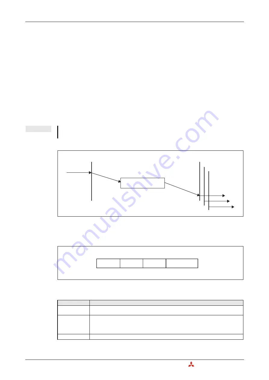
4.6.9 TIME
The TIME producer broadcasts the time stamp object. This TIME provides the simple network clock.
The time stamp contains the time of day, which is represented by a 48 bit sequence. These sequences
represent the time in milliseconds after midnight (28 bits) and the number of days since 1984-01-01
(16 bits). Only one time stamp producer is allowed in the Network.
The time and the date have to be configured by setting Un\G51 to Un\G57 (clock data).
In order to guarantee timely access to the network, the TIME is given a very high priority CAN-ID.
CANopen
devices that operate a local clock may use the TIME object to adjust their own time base
to that of the time stamp object producer.
The consuming and producing setting can be directly changed at Un\G50 (refer to section 3.5.11).
In case of time overflow (time later than 31st December 2079 23:59.59), the time returns to 1st January
2000 00:00:00. Buffer memory display for year will be 00 to 99 in all cases.
Object 1012
H
: COB-ID time stamp object
NOTE
For TIME consuming, a received time stamp before 1st January 2000 0:00.00 is set to 1st January
2000 00:00:00.
Fig. 4-19:
Time stamping
Fig. 4-20:
Bit allocation for object 1012
H
: COB-ID time stamp object
Bit/Item
Description
consume
Bit = 0: Do not consume TIME messages
Bit = 1: Consume TIME messages
produce
Bit = 0: Do not produce TIME messages
Bit = 1: Produce TIME messages
NOTE:
앫
The device needs to be active NMT master to produce TIME messages.
11-bit CAN-ID
11-bit CAN-ID of the CAN base frame. (Refer to section 4.6.1)
Tab. 4-21:
Description for object 1012
H
: COB-ID time stamp object
TIME producer
Request
TIME consumers
Indication
Time stamp
Indication
Indication
Bit 31
11-bit CAN-ID
Bit 30
Bit 10 ... Bit 0
0
H
consume
produce
Bit 29 ... Bit 11
Summary of Contents for CANopen ME3CAN1-L
Page 2: ......
Page 4: ......
Page 6: ......
Page 10: ...IV ...
Page 18: ...Abbreviations and Generic Terms Overview MELSEC L Series CANopen Module ME3CAN1 L 1 4 ...
Page 22: ...System Configuration System Equipment 2 4 MITSUBISHI ELECTRIC ...
Page 162: ...Programming Layer 2 Communication 7 24 MITSUBISHI ELECTRIC Program Fig 7 24 Example Program 1 ...
Page 164: ...Programming Layer 2 Communication 7 26 MITSUBISHI ELECTRIC Fig 7 26 Example Program 3 ...
Page 166: ...Programming Layer 2 Communication 7 28 MITSUBISHI ELECTRIC Fig 7 28 Example Program 5 ...
Page 178: ...Layer 2 Communication Programming MELSEC L Series CANopen Module ME3CAN1 L 7 40 ...
Page 184: ...Troubleshooting Error Code and Error Message Summary 8 6 MITSUBISHI ELECTRIC ...
Page 187: ......


