


Detailed Description of the Module
Buffer Memory Details: CANopen
Mode
3 – 22
MITSUBISHI ELECTRIC
3.5.15
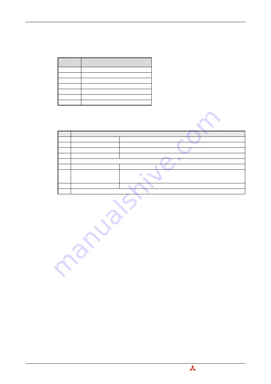
NMT Error Control Status (Un\G401–Un\G527)
The buffer memory addresses Un\G401 to Un\G527 display the Node Guarding and Heartbeat status.
The bit allocation of each buffer memory address is as follows. The description applies to the case that
the relevant bit is set to "1".
If one of the bits 2 to 7 is turned ON, the signal "NMT error of CANopen
node available" (X(n+1)0) will
turn ON.
Clearance of errors
●
To clear the error of all nodes, write 0000
H
to Un\G400 and turn ON the Clear NMT error of
CANopen
node request (Y(n+1)0).
●
To clear the error of a node, write the node number to Un\G400 and turn ON the Clear NMT error
of CANopen
node request (Y(n+1)0).
Address
(Decimal)
Description
Tab. 3-16:
Allocation of the buffer memory addresses
Un\G401 to Un\G527
401
Node 1 status
402
Node 2 status
403
Node 3 status
404
Node 4 status
:
:
526
Node 126 status
527
Node 127 status
Bit
Description
0
Guarding
Node Guarding is active
1
Heartbeat
Heartbeat is active (Will be set after the reception of the first heartbeat message.)
2
Guarding
One node guarding message is missed or toggle bit error.
3
Guarding
No response and lifetime of NMT Slave elapsed
4
NMT startup failed.
5
Guarding
The node has not the expected state.
6
Guarding
Guarding failed.
Node Guarding remote requests of the NMT Master was not received in the
expected time.
7
Heartbeat
Heartbeat is missing
8 to 15 Reserved
Tab. 3-17:
Assignment of the bits in the buffer memory addresses 401 to 527
Summary of Contents for CANopen ME3CAN1-L
Page 2: ......
Page 4: ......
Page 6: ......
Page 10: ...IV ...
Page 18: ...Abbreviations and Generic Terms Overview MELSEC L Series CANopen Module ME3CAN1 L 1 4 ...
Page 22: ...System Configuration System Equipment 2 4 MITSUBISHI ELECTRIC ...
Page 162: ...Programming Layer 2 Communication 7 24 MITSUBISHI ELECTRIC Program Fig 7 24 Example Program 1 ...
Page 164: ...Programming Layer 2 Communication 7 26 MITSUBISHI ELECTRIC Fig 7 26 Example Program 3 ...
Page 166: ...Programming Layer 2 Communication 7 28 MITSUBISHI ELECTRIC Fig 7 28 Example Program 5 ...
Page 178: ...Layer 2 Communication Programming MELSEC L Series CANopen Module ME3CAN1 L 7 40 ...
Page 184: ...Troubleshooting Error Code and Error Message Summary 8 6 MITSUBISHI ELECTRIC ...
Page 187: ......


