background image

– 14 –

Group Settings for General Equipment

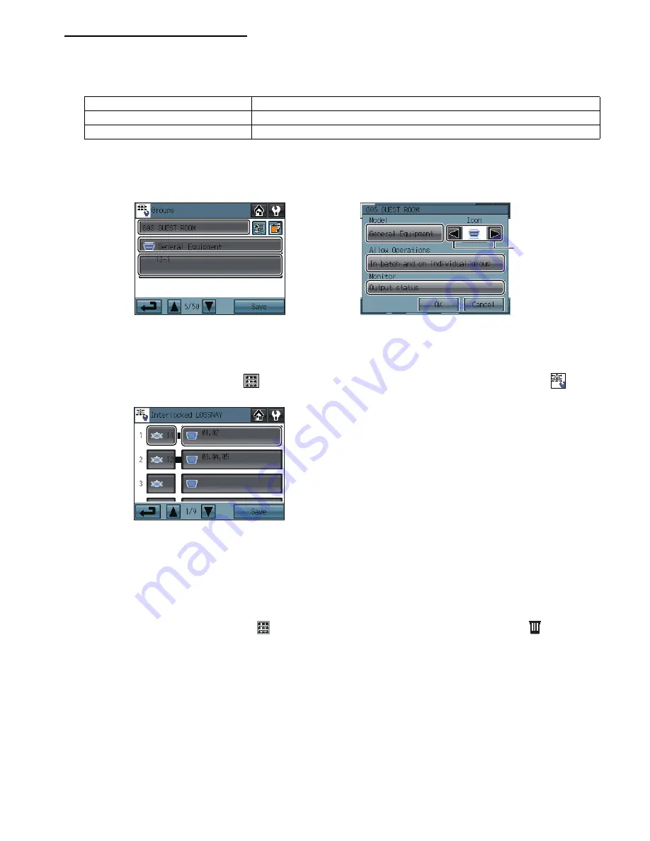
1) Touch the Model selection button (labeled 

2

 in the figure) to access the Model selection screen. 

Touch the Model selection button (labeled 

4

 in the figure) a few times so that “General Equipment” appears.

2) To change the icons, touch the Icon Selection button (labeled 

7

 in the figure), and select the desired one.

3) Touch the General equipment operation setting button (labeled 

5

 in the figure) to allow or disallow (monitor only) the user to start/

stop the connected equipment via the AT-50A.

4) Touch the General equipment display setting button (labeled 

6

 in the figure) and choose between the following ON/OFF status 

display options on the HOME screen: "Output status to the general equipment” or “Input status from the general equipment.” 

5) Touch the Unit selection button (labeled 

3

 in the figure). On the popup window that appears, check the address and the contact 

number of the DIDO controller (PAC-YG66DCA) to which the general equipment is connected.

6) After all the settings have been made, touch the Save button on the Groups screen.

(2)-3. Interlocked settings between indoor units and ventilation units (LOSSNAY and OA processing units)

To interlock the ON/OFF status of the ventilation units with the indoor units, make the settings through the “Interlocked LOSSNAY” 
screen.
* Touch the Initial Settings 2/Groups button [ 

 ] on the Service Menu, and then touch the Interlocked LOSSNAY button [ 

 ] on the 

Initial Settings 2/Groups screen to access the Interlocked LOSSNAY screen.

1) Touch the LOSSNAY button (labeled 

1

 in the figure). On the popup window that appears, check the address of the ventilation 

units to be interlocked with the operation of the indoor units.

2) Touch the Interlocked indoor unit button (labeled 

2

 in the figure). On the popup window that appears, check the address of the 

indoor units to be interlocked with the ventilation units. 
* Up to 16 indoor units can be assigned to each ventilation unit.

3) After all interlocked operation settings have been made, touch the Save button.

(2)-4. Batch deletion (Available only when AT-50A is set as a main controller)

To delete all group and interlocked operation settings collectively, follow the procedure below. 

1) Touch the Initial Settings 2/Groups button [ 

 ] on the Service Menu screen, then touch the Delete All button [ 

 ] on the Initial 

Settings 2/Groups screen. A popup message “Do you want to delete all group settings and interlocked LOSSNAY settings?” will 
appear.

2) Touch the OK button to delete group and interlock.

In batch and on individual group

Units can be turned on or off either collectively or by group from the AT-50A.

On individual group

Only certain groups of units can be turned on or off from the AT-50A.

No operations (Monitor only)

Units cannot be turned on or off from the AT-50A.

1

3

2

4

7

6

5

Group setting screen

Model selection screen

2

1

Summary of Contents for AT-50A

Page 1: ...ctric shock malfunctions smoke or fire do not operate the switches buttons or touch other electrical parts with wet hands To reduce the risk of injury or electric shock before spraying a chemical around the controller stop the operation and cover the controller To reduce the risk of injury or electric shock stop the operation and switch off the power supply before cleaning maintaining or inspectin...

Page 2: ...ical noise interference To reduce the risk of electric shock shorting or malfunctions keep wire pieces and sheath shavings out of the terminal block To reduce the risk of shorting current leakage electric shock or malfunctions keep the cables out of contact with controller edges To reduce the risk of electric shock malfunctions or fire seal the gap between the cables and cable access holes with pu...

Page 3: ...e controller 1 2 6 Installation Manual This manual 1 7 Instruction Book 1 8 CD ROM Instruction Book Installation Manual 1 2 Mounting bracket 1 AT 50A Power LED Touch panel For connection to the M NET A B Terminal for connection to the M NET cable non polarized External output adapter cable access hole External input adapter cable access hole Controller cover mounting screw SD memory slot for progr...

Page 4: ...or units apply An M NET interface sold separately is required 1 50 M NET remote controller Assign an address that equals the address of the main indoor unit with the lowest address in the group plus 100 Add 150 instead of 100 to set a sub remote controller 101 200 Sub system controller Assign an address that equals the lowest number of the group to be controlled plus 200 201 250 DIDO PAC YG66DCA A...

Page 5: ...nsure the M NET transmission cables and external input output cables are long enough to reach the controller Have extra cables to extend these cables as necessary To install the controller according to the instructions provided in sections a and b 1 above Include an extra 30 cm 12 in of cable to provide adequate slack in the cable Remove the sheath on the M NET transmission cable up to 20 cm 8 in ...

Page 6: ...the terminal block M NET transmission cable is non polarized Insert the cables in the groove on the controller so they will not be pinched when the cover is installed To route the cable along the wall surface Secure the cables in place with a cable cover and seal the gap between the cable cover and the controller with putty 5 Replace the cover Snap the cover into place and attach it to the control...

Page 7: ...ue between 0 2 and 1 seconds 4 Sample circuit recommended Mode External input signal setting Notes 1 Do not use external input Factory setting 2 Emergency stop Normal operation signal level signal When the units are not operating after receiving an emergency stop signal the ON OFF operation from the local remote controller will not be allowed and the ON OFF and Prohibit Permit settings on the AT 5...

Page 8: ...during operation The maximum length of extension cable is 10 m 32 ft Use a cable of 0 3 mm 22AWG or thicker Insulate the area with vinyl tape where the controller cable and the extension cable are connected Relays lamps diode extension cables are field supplied Note The AT 50A has a slot for an SD memory card at the bottom that can be used to update software Refer to the Installation Manual for th...

Page 9: ... ON OFF Mode Set Temp and Filter Reset 12 External input mode Selects the external input mode 12 Filter sign Displays or suppresses the Filter sign on the HOME screen 12 Dry mode Includes or excludes Dry mode as an option for the operation mode 12 Set temperature range Schedule Selects the settable temperature range Standard 19 C 67 F to 28 C 83 F Low 8 C 46 F to 30 C 87 F Manual Settable to any a...

Page 10: ...enu Touch or HOME screen GRID zoom out view GRID zoom in view LIST view GROUP view Main Menu screen Login Page screen 1 Password Change screen Service Menu Service Menu screen Initial settings 1 Basic system Initial settings 2 Groups Groups Interlocked LOSSNAY Delete All System view Malfunction log Gas Amount Check Maintenance Test run Software update Button name Main Menu Service Menu Password Ch...

Page 11: ...begin the communication g The message shown above will appear on the screen displaying the initialization progress When initialization is complete the screen will automatically return to the HOME screen Initialization will take up to five minutes To change settings later perform a test run or verify the maintenance information 1 Touch MAIN MENU button on the HOME screen 2 Touch SERVICE MENU button...

Page 12: ...o ON OFF Mode Set Temp and Filter Reset External Input Mode 1 Press the External Input setting button labeled 1 in the figure to select between Not used Emergency Stop Level signal ON OFF Level signal and ON OFF Prohibit Permit Pulse signal Refer to the Installation Manual for detailed information on how to connect the AT 50A to external devices Filter Sign Display 1 Press the Filter Sign Display ...

Page 13: ...up Indoor units LOSSNAY units and general equipment cannot be combined in one group General equipment groups cannot include remote controller or system controllers Touch Page turn button to turn the pages and follow the directions below to make the settings for each group Group Name 1 Touch the Group Name Input button labeled 1 in the figure and enter the group name in the screen up to 16 characte...

Page 14: ...he Initial Settings 2 Groups button on the Service Menu and then touch the Interlocked LOSSNAY button on the Initial Settings 2 Groups screen to access the Interlocked LOSSNAY screen 1 Touch the LOSSNAY button labeled 1 in the figure On the popup window that appears check the address of the ventilation units to be interlocked with the operation of the indoor units 2 Touch the Interlocked indoor un...

Page 15: ...at support the test run function 2 Operation mode Touch this button to switch the operation mode 3 Pipe temperature The pipe temperature of the indoor unit with the lowest address in a given group will appear 4 Advanced settings Touch this button for advanced settings Display Function A Indoor temperature Indoor air temperature will appear B Unit address up down arrows Use the up down arrows to se...

Page 16: ... OK button If the message The DIP switch 4 is set to OFF appears check to make sure that the DIP switch 4 is turned to ON The DIP switch is located at the left bottom of the controller under the cover 4 Touch the OK button on the confirmation screen 5 Touch the OK button on the popup message to begin the update process 6 The lit LEDs on the three buttons F1 F2 and Collective ON OFF will indicate a...

Reviews: