background image

GUIDE TO INSTALLATION AND OPERATION 

FRS-3901  |  

89


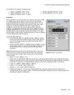
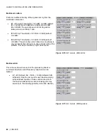
Upmix Configuration 

 
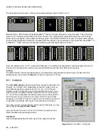
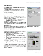
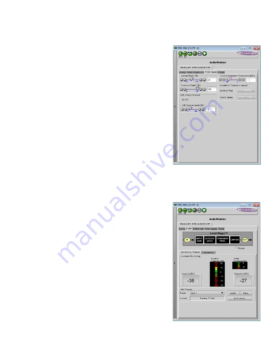
To set up the parameters of the upmix, go to the PGM1-Upmix tab in 
the Audio Modules panel.  

When Upmix is available (-DUP option active, and

 Disable Upmix 

Hardware

 not selected), the following adjustments are available. 


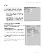
Surround Field Adjustments 

The “surround field” can be adjusted with the Center channel Width 
control and the Surround channel Depth control. 
 

AutoMAX-II Transition Speed 

When the upmix operates in AutoMAX-II

tm

 mode, the speed of the 

transitions from 2.0 to 5.1, and 5.1 to 2.0, can be configured to provide 
smooth and unobtrusive changeovers. 


Set the “Upmix-to-Pass” and “Pass-to-Upmix” transition speeds 

independently, over the range 

Instant

 to

 Very Slow


5.1/2.0 Detection Threshold 

This parameter is used when the upmix operates in AutoMAX-II

tm

 mode 

to detect silence on some of the 5.1 channels to determine if 5.1 or 2.0 
is detected. 
 

LFE Output Channel 

The bass enhancement signal for the LFE channel is derived from the 
Left, Center and Right channels. The LFE checkbox and LFE Channel 
Level slider control the LFE output 

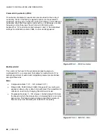
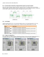
6.6.3  Loudness Monitoring 

 
Loudness monitoring and ALC are accessed through the various PGMX 
tabs that appear in the Audio Modules panel.  


The tabs that appear are determined by the configuration 

selected in the Config tab 


Each program has a tab of its own, e.g. PGM1, PGM2, PGM3, 

etc. 


If PGM1 is 5.1, and its LFE is not linked, the LFE will have its own 

tab, PGM1-LFE 

 
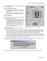
Automatic Level Control using the Jünger Audio Level Magic

tm

 system 

can be enabled or disabled for each program.  


Select the Bypass checkbox beneath the graphic to disable the 

ALC 

 
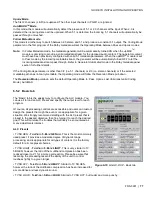
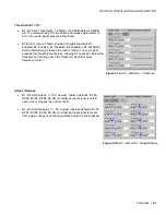
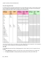
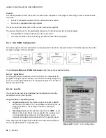
When enabled, the loudness meters display the input loudness (before 
ALC processing), the dynamic correction applied by the ALC, the limiter 
correction applied by the ALC, and the program output loudness (after 
ALC processing).  The input and output loudnesses are given in 

LKFS

based on ITU-R BS.1770. 


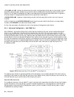
Figure 6-21 JA-ALC module - Upmix


Figure 6-22 JA-ALC module - Loudness 

Summary of Contents for FRS-3901

Page 1: ...ed Audio Metadata Processor Guide to Installation and Operation M932 9900 310 16 June 2014 Miranda Technologies 3499 Douglas B Floreani St Laurent Québec Canada H4S 2C6 Tel 514 333 1772 Fax 514 333 9828 www miranda com 2014 Miranda Technologies ...

Page 2: ...rmonic current injection EN 61000 3 3 Limitation of voltage changes voltage fluctuations and flicker EN 61000 4 2 Electrostatic discharge immunity EN 61000 4 3 Radiated electromagnetic field immunity radio frequencies EN 61000 4 4 Electrical fast transient immunity EN 61000 4 5 Surge immunity EN 61000 4 11 Voltage dips short interruptions and voltage variations immunity Manufactured under license ...

Page 3: ...l panel 9 4 1 Overview 9 4 2 Menu for local control 9 5 Remote control using iControl 10 5 1 The iControl graphic interface window 10 5 2 Video Input Output panel 13 5 2 1 Deglitcher tab 13 5 2 2 Freeze tab 15 5 2 3 Timing tab 16 5 3 Metadata panel 17 5 3 1 GPI tab 17 5 3 2 AFD tab 18 5 4 Video Processing Panel 21 5 4 1 Basic tab 21 5 4 2 Advanced tab 22 5 5 Audio Processing panel 22 5 5 1 Audio P...

Page 4: ... panel 65 6 Audio Modules 67 6 1 Dolby E and Dolby Digital decoder 67 6 1 1 Control tab 67 6 1 2 Dolby E tab 68 6 1 3 Dolby Digital tab 69 6 1 4 PCM tab 69 6 2 Dolby Digital and Dolby Digital Plus encoder 70 6 2 1 Shuffler Inputs 70 6 2 2 Configuration 70 6 2 3 Status 71 6 3 Dolby E encoder 72 6 3 1 Input channel selection 72 6 3 2 Configuration 72 6 3 3 Status 73 6 4 Upmixing using Linear Acousti...

Page 5: ...NEX 1 FRS 3901 Local User Interface 96 ANNEX 2 Installing the Optical Interface 98 ANNEX 3 Installing the Audio Module 100 ANNEX 4 Dolby Digital Main Channel Output Functions 103 ANNEX 5 AFD Flags 104 ANNEX 6 Loudness Logging and the Miranda Audio Loudness Analyzer 106 ...

Page 6: ...GUIDE TO INSTALLATION AND OPERATION FRS 3901 ...

Page 7: ... lip sync between the channels Each channel can be delayed independently to correct any lip sync issues All audio channels can be mixed and shuffled to provide 16 channels for embedding in the video output An Automatic Preset Recall feature provides basic automation to select user preset based on the status of the incoming audio When genlocked to an external reference or to the frame reference usi...

Page 8: ...randa Wideband processing Optional loudness measurement of up to 4 audio programs and logging with iControl Loudness compliant to EBU R128 ATSC A 85 and ARIB TR B32 up to ITU R BS 1770 3 Optional on board Audio dynamic processor option compressor limiter expander Automation capabilities based on audio signal type detection Audio delay adjustments of up to 2 seconds to compensate for lip sync issue...

Page 9: ...gure 1 1 FRS 3901 Functional Block Diagram 1 4 Front Card edge Interface The front card edge of the FRS 3901 incorporates two elements Status LED see section 3 2 Select Button see section 4 Figure 1 2 Front card edge layout Select Button IRD 3802 Status LED Status Select FRS 3901 ...

Page 10: ... The card has connectors which plug into a mid frame mother board for distribution of power and for connection to the controller card and a second connector which plugs directly into the rear connector panel for input and output The rear connector panel must be installed with the card out of the frame To remove an existing card from the slot tilt up the swivel handle on the front of the card to le...

Page 11: ... 170M SMPTE 318M ITU 624 4 BUT 470 6 for standard definition signals and SMPTE 274M SMPTE 296M for high definition signals and is used to phase the HD SD SDI outputs to the studio A reference mismatch may occur if there is a difference between the input video format s frame rate and the reference format s frame rate When a mismatch occurs the output will freeze to the reference frame rate and prod...

Page 12: ...ried on an RJ 45 connector The pinout is shown in the table Fiber I O Fiber optic inputs and outputs The FRS 3901 3SRP F rear panel incorporates a fiber optic interface The interface consists of two parts A socket on the rear panel into which an SFP interface module is plugged An SFP Small Form factor Pluggable module into which the optical fibers are plugged and which incorporates the optical ele...

Page 13: ...al Audio Module Installation The FRS 3901 may be equipped with an optional audio module The audio module must be installed into a socket on the FRS 3901 card See ANNEX 4 Installing the Audio Module beginning on page 100 for complete installation instructions ...

Page 14: ... can be flagged on the FRS 3901 affect the LED status If a cell is gray the error condition cannot cause the LED to assume that status If more than one LED status is possible for a particular error condition the status is configurable See Section 5 16 for details The factory default status is shown by a The LED will always show the most severe detected error status that it is configured to display...

Page 15: ...card flashes yellow The local control panel displays a menu that can be navigated using the four pushbuttons located beside the display The functionality of the pushbuttons is as follows Used for menu navigation and value modification SELECT Gives access to the next menu level When a parameter value is shown pushing this button once enables modification of the value using the and buttons a second ...

Page 16: ...e 5 1 The window identification line gives the card type FRS 3901 and the slot number where the card is installed in its Densité frame There are four main sections in the window itself identified in figure 5 1 Section 1 The top section displays six icons on the left These icons report different statuses such as card communication status input signal and reference signal format and statuses In some...

Page 17: ...d The iControl interface can be used to operate the card yellow Local card control active The card is being controlled using the Densité frame control panel as described in section 4 Any changes made using the iControl interface will have no effect on the card Icon 2 Input status green Signal detected and valid Beneath the icon the format will be indicated as 3G HD or SD and the specific format de...

Page 18: ...icon appears red return the card to Miranda and specify the error code Section 2 The left portion of the window contains all the parameter groups which become highlighted when they are selected the main panel 4 then displays the group s set of parameters Each of the groups is described in detail below Section 3 The lower left corner of the window identifies the Preset currently in use or Custom if...

Page 19: ...lid external reference signal must be installed or the URS signal must be selected as the reference in the Reference panel see section 5 13 Deglitcher select OFF or ON from the pulldown For this mode to function correctly the following requirements must be met The two inputs must be synchronized to the reference They must be phased within one line of each other They must be phased to within line o...

Page 20: ...iControl Input Deglitcher Use the controller menu in Annex 1 video timing in timing to ref When the deglitcher mode is on each of these sources will display the alignment offset between the reference signal and the input signal Knowing the offset for both input signals you can determine if they are in the same clean switch region If so any hot switch between those two signals will be glitchless To...

Page 21: ...ermine that this switch will be clean because the two sources are inside the same clean switch region Ref signal Signal A Signal B H line H 0 Line 0 40us 31 76us 50us clean switch region 2 H line H 0 V 1 H 0 V 1 H 0 Line 1 H line clean switch region 3 95 28us 5 2 2 Freeze tab Freeze type This is a pull down menu with four options FIELD 1 FIELD 2 FRAME and BLACK It determines the manner in which th...

Page 22: ...lider controls each with a data reporting box which shows the current value and into which values can be typed directly The total delay is reported at the top of the window Vertical lines With this adjustment a value ranging from 16 to 16 lines compared to the reference or the processing delay may be set This adjustment can be used in conjunction with the horizontal timing adjustment Horizontal µs...

Page 23: ... de embedding of GPI data in the output and input data streams For each of the three GPIs Mode use the pulldown list to select the operating mode for this GPI OFF the GPI is passed through untouched De embed a pre defined user binary group bit from timecode within the incoming signal is de embedded and appears on the rear panel GPI port When De embed is selected use the Bit pulldown list to select...

Page 24: ...t use the AFD flag to perform any picture manipulation The AFD flag is implemented differently in HD and SD In HD the AFD flag SMPTE 2016 is sent as an ancillary packet normally found on line 11 in the vertical ancillary space In SD the AFD flag is sent as a Video Line Index VLI signal RP 186 as a Wide Screen Signaling WSS signal ITU R BT 1119 2 for 625 only and as an AFD packet SMPTE 2016 Note Th...

Page 25: ...e selected in the Mode pulldown above In AUTO mode it is labeled DEFAULT and shows the current default AFD code to be used if no valid AFD code is detected at the input In INSERT mode it is labeled FORCED and shows the code that is forced onto the output regardless of the actual input code or if one is present Change Click the Change button to open the Select AFD panel showing the available AFD co...

Page 26: ...r to the user manual Warning in blue Incoming DVITC time code may unknowingly be replaced by the insertion of SMPTE 2016 AFD flag In order to avoid any problems make sure the line number of any incoming time code is known Dolby Metadata insertion may overwrite incoming TC VLI on insertion line Refer to the user manual Warning in blue Incoming DVITC time code or VLI signal may unknowingly be corrup...

Page 27: ...mode This may cause adverse effects so it is wise to return the gain offset values to their default values zero after changing the proc mode 5 4 1 Basic tab All Gain Sets Luma and Chroma gains or G B and R gains to a specific value When other gains are individually set ALL GAIN reflects the average value of the combined gains The choice of processing mode made at the top of the panel determines wh...

Page 28: ...e the user of the situation The 32 processed audio channels can be assigned later to the Dolby E or Dolby Digital and Dolby Digital Plus encoder modules the 3G HD output embedder the SD output embedder or the discrete AES outputs You can configure the audio processor differently for an SD input than for a 3G HD input The card will remember the different parameters and will load them automatically ...

Page 29: ...he Alarm Config panel Sect 5 16 Under the Audio Proc tab are grouped controls for several aspects of the FRS 3901 s audio processing levels delay silence detection All of these parameters are adjusted individually for each channel and channels are accessed in groups of four via the first row of tabs in the panel Below these tabs are the three tabs that access the parameters themselves In addition ...

Page 30: ...tment Frame Delay Range Range 59 94 Hz 50 Hz 1 12 to 2000 ms 19 to 2000 ms 2 45 to 2000 ms 59 to 2000 ms 3 78 to 2000 ms 99 to 2000 ms 15 479 to 2000 ms 579 to 2000 ms Fine adjusts the delay in audio sample increments from 100 to 100 samples 5 5 3 Audio Proc Silence tab This tab sets the card s behavior in the event of a loss or absence of audio signal The Signal Presence indicators are then trigg...

Page 31: ...pplied on the downmix output level OFF Downmix output level is not normalized Clipping may occur depending on the input channel levels and the selected mix levels Level A Downmix output level is normalized based on the applied mix levels to provide a uniform output over the range of mix levels available Clipping will never occur even with full scale input channels and mix levels Level B Downmix ou...

Page 32: ...oRo Enables the downmix of 5 1 channels into an LoRo Left only Right only stereo pair which is a conventional stereo signal The input signals on the channel pair selected as the Output Channels are discarded Dialnorm this pulldown selects the dialog normalization level Select OFF to prevent the downmix from applying the dialnorm OFF 1 dBFS 2 dBFS 3 dBFS 31 dBFS Center Mix Level sets the center cha...

Page 33: ...by E alignment Audio Type Status PCM the audio channel carries PCM audio orange Dolby E the audio channel carries Dolby E encoded audio blue AC3 the audio channel carries Dolby Digital encoded audio violet NPCM the audio channel carries Dolby Digital Plus or non PCM other than Dolby E or Dolby Digital yellow Dolby E Alignment When Dolby E audio is present this panel will display the offset delay b...

Page 34: ...tified as FRS 3901 OPT ALC X where X can be 2 6 8 or 16 input channels The table shows the ALC models available Model Description Program types supported FRS 3901 OPT ALC 2 2 Channel ALC up to 2 independent programs Mono 2 0 FRS 3901 OPT ALC 6 6 Channel ALC up to 6 independent programs Mono 2 0 3 0 4 0 5 1 FRS 3901 OPT ALC 8 8 Channel ALC up to 8 independent programs Mono 2 0 3 0 4 0 5 1 7 1 FRS 3...

Page 35: ...m input loudness before ALC processing the dynamic correction applied by the ALC the ALC limiter correction and the program output loudness after ALC processing The input and output loudness are given in LUFS or LKFS depending on the modes selected in the Config tab Loudness meters are integrated over a sliding window period which is also mode dependent Dynamic and limiter corrections are always g...

Page 36: ...ctory preset Light Standard Heavy that is closest to the desired objective then fine tuning it to reach the desired goal This will minimize the troubles that will likely be encountered as many adjustments interact ALC Bypass Checking this box bypasses the ALC program processing the input channels pass through to the output unaltered Target Loudness Sets the target output loudness This value sets t...

Page 37: ...he threshold below which the ALC will not increase loudness This prevents quiet portions of programs and noise from being unintentionally boosted If the input program loudness is under the Freeze Threshold for more than 30 seconds the ALC will smoothly return to 0 dB of loudness correction Limiter Threshold The Limiter Threshold will limit the output loudness under the selected threshold This avoi...

Page 38: ...ssor set to a very high compression ratio typically 1 For example if the limiter threshold is set to 20 dBFS and the input signal level is 10 dBFS 10 dB above the threshold the signal level at the output of the limiter will be 20 dBFS Use the Limiter Threshold slider to set the threshold from 20 dBFS to 0 dBFS 1 dB steps Compressor Audio compression is a method of reducing the dynamic range of a s...

Page 39: ...or example if the expander threshold is set to 40 dBFS and a ratio of 2 1 and the input signal level is 60 dBFS 20 dB below the threshold the signal level at the output of the expander will be reduced to 80 dBFS Then if the input signal level suddenly increases to 30 dBFS 10 dB above the threshold the signal level at the output of the expander will go back to 30 dBFS Use the Ratio pulldown to set ...

Page 40: ...ayer 1 tab layer 2 tab layer 3 tab For example the panel shown in the figure on the right would be described as Config Delay 5 9 1 Config tab Input Presence Status icons are provided to indicate sources where Dolby Metadata is present and valid The following are shown VANC Stream RS 422B Decoder grey if not installed Source This area allows source selection The currently active pathway is shown in...

Page 41: ...pMAX tm mode is dictated by the coding mode parameter of the probed metadata stream When the metadata stream coding mode is 2 0 the upMAX tm mode is set to Upmix and the generator will be turned on to generate 5 1 metadata for the upmixed audio content It is the responsibility of the user to configure the generator with the proper 5 1 metadata parameters If the metadata stream coding mode is 3 2 t...

Page 42: ...ogram Configuration and the Video Frame Rate of the Metadata bitstream Depending on the Program configuration one to eight programs are included in a Metadata bitstream The Program Select zone allows the selection of one Metadata program The text boxes below the program select buttons report on the data rate coding mode and dialnorm value of the selected program Config Probe Audio Processing This ...

Page 43: ...tection Config Probe Bitstream Info This panel reports the status of the metadata bitstream Bitstream Mode Center Downmix Level Surr Downmix Level Dolby Surr Mode Copyright Bit Original Bitstream Audio Production Info Mix Level Room Type Additional bitstream information is found in the Extended BSI tab Figure 5 26 Config Probe Dynamic Range Figure 5 27 Config Probe Bitstream Info ...

Page 44: ...e Program Configuration The text box below it shows the Video Frame Rate which is set automatically by the card Use the Program Select buttons to select the program to configure Use the Coding Mode and Dialnorm pulldowns to set these parameters in the generator output Config Generator Audio Processing This panel allows configuration of the audio processing parameters Extended Bitstream info 1 Exte...

Page 45: ...tandard Film light Music standard Music light Speech RF Overmod Protection Config Generator Bitstream Info This panel allows configuration of the metadata bitstream info parameters Use the pulldowns to select the appropriate values Bitstream Mode Center Downmix Level Surr Downmix Level Dolby Surr Mode Copyright Bit Original Bitstream Audio Production Info Mix Level Room Type Figure 5 30 Config Gen...

Page 46: ...ia the Edit Presets Labels button at the bottom of the tab In addition the FRS 3901 is preloaded with two fixed data sets named Factory 2 0 and Factory 5 1 The Current Generator Preset databox at the top of the tab reports the current preset in use If all parameter values do not match the preset values the box will show Custom The Generator Presets pulldown gives access to all seven available pres...

Page 47: ...a iControl The Copy profile from line shows the current FRS 3901 card The Profiles column contains a pulldown that lists the profiles that are available to copy The list includes the generator plus the 5 metadata presets You can save the selected profile to disk for future recall Click the Save profile to disk button and select a disk location and file name to save the file You can recall a previo...

Page 48: ...ine Select the VANC line in which the metadata will be inserted The range depends on the output format 3G HD lines 9 to 20 SD 525 lines 12 to 19 SD 625 lines 8 to 22 SDID Select the VANC metadata packet SDID to be inserted The SDID is used to specify the relationship between the VANC metadata stream and the first channel of its associated audio program SDID Associated channel pair 01 No associatio...

Page 49: ...el source ABUS Select and Channel selected in sub menu SOURCE A SUM A B The output channel is the sum of the two channels sources ABUS Select and Channel selected in sub menus SOURCE A and SOURCE B If you select this option the SUM A B Level pull down is activated allowing you to reduce the level of the summed output 0dB 3dB or 6dB Mix The output channel is a mono mix of the ABUS Select and Channe...

Page 50: ...at least one audio channel will be embedded at the output For SD outputs the number of bits to be embedded must also be selected and so the options in the pulldown are OFF Auto 20 bits Auto 24 bits 5 11 Loudness Panel Note In order to use the loudness measurement capabilities of the FRS 3901 the Loudness Measurement Option must be installed See section 5 17 3 on page 61 for details The FRS 3901 al...

Page 51: ...user s needs The range of available values is shown in the chart Global Control The FRS 3901 can monitor loudness on up to four programs specified by the user In this panel select which programs will be active using the PGM 1 to PGM 4 checkboxes The tabs for the selected programs will become active allowing each program to be defined Enable Loudness Monitoring turns all loudness monitoring functio...

Page 52: ...each activated by selecting the appropriate checkbox in the LOUDNESS CONFIG panel Use these panels to define the programs whose loudness will be monitored by this FRS 3901 Program Settings Operation Mode Use the pulldown to select to source of the program definition Manual Use the Manual Coding controls to define the program channel Path Use the path defined in the Dolby Metadata panel see section...

Page 53: ...cted its Dialnorm and Coding Mode are extracted and displayed in the data boxes below the switcher Note that If the user selects Metadata path as the source but no metadata is present the selection defaults to Manual mode In Manual mode there is no dialnorm to extract Measurements The Measurements area displays results from the loudness measurements performed on the selected program according to t...

Page 54: ... when the reference changes when the global config is changed See ANNEX 6 Loudness Logging and the Miranda Audio Loudness Analyzer beginning on page 106 for detailed instructions on activating logging and analyzing the logged data files 5 12 Fingerprint panel Fingerprinting technology on this card functions in conjunction with iControl iControl 4 0 and higher is required FRS 3901 streaming is ON b...

Page 55: ...e height but can be placed anywhere within the picture 5 13 Reference panel This panel allows the selection of the reference to be used by the FRS 3901 Icons in the Reference Presence area indicate which references are available to this FRS 3901 Use the radio buttons in the Reference Source area to select from the following options Auto this mode selects the first source detected in this order of ...

Page 56: ...Meter RALM panel displays audio output level meters for up to 8 channels Channels are displayed in pairs so up to four meters will be present in the meter display window The source for each meter is selected using the pulldowns in the RALM Remote Control area at the bottom of the control panel OFF Embedded CH 1 2 up to CH 15 16 The meter is divided into three zones and the dividing points and colo...

Page 57: ...wn by a marker beside the meter and its position can be set under the Meter Ballistics Config tab The Phasemeter located at the bottom of the RALM meter display is a small meter that represents the phase correlation factor between the two channels of a pair 180 90 0 Note The level and phase meters are disabled for channels carrying non PCM audio Dolby E Dolby Digital Dolby Digital Plus or other no...

Page 58: ...rner of the panel displays the last loaded preset Any change to the card configuration after a preset is loaded will change the display to Custom instead of the preset value Select any one of the five presets using the pull down list The name of the currently selected User Preset is shown on the pulldown box Click Load to load the contents of the selected User Preset into the FRS 3901 All paramete...

Page 59: ...d the Current Generator Preset box in the Presets tab as well as the Generator tab label will all read Custom The warning box gives you three options for dealing with the situation Option 1 abort the save process so that you can go back and manually save the metadata parameters see instructions on page 40 Option 2 go ahead and save anyway but be aware that if you recall this User Preset you will p...

Page 60: ...nt to work with the current card Save Profile to Disk Click this button to open a Save dialog allowing you to specify a file name and location to which the selected profiles for this card will be saved Hint It is a good idea to create a folder for these files because they are not explicitly identified as FRS 3901 profiles and will be difficult to find and identify if not clearly named and convenie...

Page 61: ... information as is shown for the current card in the Copy profile from line i e one of the following Current User1 User2 User3 User4 User5 All The Select column includes a checkbox to identify which FRS 3901 cards you wish to copy profiles into from the current card For convenience a Select all checkbox is provided in the column header Click Copy to copy the selected profiles from this card into t...

Page 62: ...p instructions are given below The Automatic Preset Recall APR feature uses the status of audio appearing at the input audio channels to determine whether activation of a preset is required The user specifies the combination of audios that must appear on all 16 channels using a concise Presence Type string notation in a data box one for each of the two user presets For reference the current input ...

Page 63: ...e that you may activate either Automatic Preset Recall as described here or select a user preset to be activated by a GPI in the Load Presets section of the Metadata GPI tab see section 5 3 1 on page 17 but only one of these may be active at a time If User Preset activation via GPI is active when you click Enable Preset Recall in this tab a warning box will appear to remind you that enabling this ...

Page 64: ...begin note that the Audio Type detector and the Audio Presence detector are both located at the input to the card The idea is to calculate the time delay as the audio passes through the FRS 3901 between the time at which the audio condition is detected and the time when the audio arrives at the location where the changes in processing need to be applied The new preset should only be applied then s...

Page 65: ...Duration will be set to 30 msec and the Threshold to 72 dBFS Assuming the total processing delay of the FRS 3901 is set to 66 msec to give enough reaction time between the detection of the silence and the application of the preset the Automatic Preset Recall should be configured as shown in the picture below The delay to apply the preset has been optimized to take into account the No signal Durati...

Page 66: ... Note that this option is available for 2 6 8 or 16 channels A separate license key is required for each of these and the data window below the Enter key data box will indicate which is currently enabled e g ALC FRS 3901 OPT ALC 16 for the 16 channel option If the currently enabled option is 2 6 or 8 channels the Enter key data box will be available to upgrade to a greater number of channels Figur...

Page 67: ...GUIDE TO INSTALLATION AND OPERATION FRS 3901 61 5 17 3 Loudness Measurement option This option enables the Loudness Measurement feature of the FRS 3901 Figure 5 59 Loudness Measurement option ...

Page 68: ...cted individual alarms to the status LED located on the front card edge The Card LED status is shown at the bottom of the alarm tree in the Status Name column Overall Alarm This column allows configuration of the contribution of each individual alarm to the Overall Alarm associated with this card The Overall Alarm is shown in the upper left corner of the iControl panel and also appears at the bott...

Page 69: ... them Log Events iControl maintains a log of alarm events associated with the card The log is useful for troubleshooting and identifying event sequences Click in the checkbox to enable logging of alarm events for each individual alarm At the bottom of the window are several other controls Overall alarm and GSM contribution follow card LED Click in the checkbox to force the Overall alarm and GSM co...

Page 70: ... with all the other settings Get alarm keys Click this button to open a save dialog where you can save a file containing a list of all alarms on this card and their current values along with an Alarm Key for each The alarm keys are useful for system integration and troubleshooting The file is saved in csv format OK Apply Cancel OK accepts the settings and closes the window once the card confirms t...

Page 71: ...le Identifies the audio module currently installed on the FRS 3901 if any Label type the label that is shown for this FRS 3901 when it appears in iControl applications Short Label type the short form label that iControl uses in some cases 8 characters Source ID type a descriptive name for this FRS 3901 Comments type any desired text The remaining data boxes show manufacturing information about thi...

Page 72: ...rvice for this FRS 3901 to register itself on a user specified Jini lookup service using the following syntax in the data box jini ip_address where ip_address is the ip address of the server running the lookup service e g Remove select one of the services listed in the window by clicking on it and click Remove to open a query box allowing you to delete it from the window Figure 5 67 Joining Locato...

Page 73: ...e 84 N 2 6 or 8 referring to the number of channels processed 6 1 Dolby E and Dolby Digital decoder Identified as MOD DOLBY DEC 2 on the module tab The decoder supports Dolby E Dolby Digital or PCM signals Any other non PCM signal will be lost through the decoder module its outputs will be muted For a Dolby E input signal the decoder outputs a metadata bitstream which may be used by the audio proc...

Page 74: ...d Dolby Digital bitstream the channel data will be passed to the decoder output as a PCM signal The Listening Mode parameter selects the main channel output listening mode It is active only for a Dolby Digital input signal Full is the standard mode Monitoring in 3 Stereo mode reproduces only the left right and center channels the surround channels are muted In Phantom mode the center channel outpu...

Page 75: ...al Status section indicates status information for the Dolby Digital bitstream selected at the bottom of the Control tab Coding Mode Data Rate Bitstream Mode Dialnorm value Dolby Surround Mode Surround EX Mode Preferred Stereo Downmix Mode 6 1 4 PCM tab The PCM tab section indicates the output audio assignment of the Dolby Decoder module when its input is a PCM signal Figure 6 4 Dolby Decoder PCM ...

Page 76: ...heckbox or Pass through Test signals at 18 20 dBFS and silence are available for each mode Encode test modes will generate a test bit stream containing a 1 kHz sine wave for full bandwidth channels and 100 Hz for the LFE channel of a 5 1 program In Pass through test modes it will generate a 1 kHz PCM sine wave at its outputs When the encoding mode changes the output mutes and resumes in the select...

Page 77: ...ule s behavior when its selected Metadata Source is lost or corrupted Use last valid Metadata Stop Encoding Encoding Latency The Dolby Digital and Dolby Digital Plus encoding latency is 187 msec The encoding latency is automatically compensated to avoid lip sync issues when the video frame delay Timing tab is set to at least seven 7 frames for 59 94 Hz formats and at least six 6 frames for 50 Hz f...

Page 78: ... This parameter specifies the number of bits per word used in the Dolby E bitstream When using an output data width of 16 bits the available program configuration will be limited to those which require a maximum total of 6 channels 48 kHz Pull down When Pull down mode is enabled the encoder will output the Dolby E bitstream at a sample rate of 1000 1001 48 kHz Metadata Source Metadata is the only ...

Page 79: ...ur different processing solutions Pass Mode Select the input channels to the L R C LFE Ls and Rs inputs with the pull down menus These channels are passed through unaltered and are assigned to the output channels selected using the Output Channels pulldown Upmix Mode Select the input channel pair to the L R inputs with the pull down menu The resulting 5 1 channels are assigned to the output channe...

Page 80: ...n for further details page 35 If the Coding Mode parameter in the Dolby Metadata panel is other than 3 2 i e 5 1 channels or 2 0 i e stereo channels or if the selected metadata path does not carry metadata the Operating mode will follow the Reversion Mode pull down Coding Mode Metadata Operating Mode 3 2 PASS 2 0 UPMIX 1 1 1 0 3 0 2 1 3 1 2 2 or metadata is not present Reversion Mode The Reversion...

Page 81: ...oustic Up to 5 1 N A MOD LA ALC 6 DUP 6 Channel ALC and upmix licensed by Linear Acoustic Up to 5 1 N A MOD LA ALC 8 8 Channel ALC licensed by Linear Acoustic Up to 5 1 Up to 2 0 MOD LA ALC 8 DUP 8 Channel ALC and upmix licensed by Linear Acoustic Up to 5 1 Up to 2 0 Depending on the model different channel configurations are possible as listed in the table above The 6 channel ALC supports only a ...

Page 82: ...audio If non PCM audio like Dolby E or Dolby Digital is fed to the module it will be ignored and silenced to prevent interference with the other PCM audio channels Latency The MOD LA ALC module processing latency is automatically compensated to avoid lip sync issues when the additional video frame delay Timing tab is set to at least one 1 frame 6 5 1 Config tab The ALC PGM x Mode pulldowns specify...

Page 83: ...metadata the Operating mode will follow the Reversion Mode pull down The Reversion Mode pull down sets the default Operating Mode to Pass Upmix Last Valid Last valid Coding Mode AutoMAX 6 5 2 Basic tab The Basic tab is the easiest way to configure the ALC module You can use it to load an ALC Preset and specify the output level for each program Of course all processing controls are accessible and u...

Page 84: ...sitcoms of every type and talking head programs of every type Linear Acoustic has already done much of the heavy lifting and provides presets based on their own listening and feedback from customers over the past few years Certain parameters such as crossover frequencies and channel coupling are not adjustable and are hard coded to the most appropriate values That being said access to all adjustab...

Page 85: ...point at which the AGC release is made extremely slow to prevent increasing background noise and allow the AGC to return to unity gain Freeze Threshold 0dBFS to 90dBFS default 42dBFS Freeze stops all gain change i e when the audio drops to silence and remains frozen at its current gain value until the threshold is exceeded NOTE Adjust Gate and Freeze to match plant practices Very quiet audio such ...

Page 86: ...ltiband AGC This section is the heart of the dynamics processing engine A multiband AGC i e compressor that allows for medium ratio 3 1 is default adjustment of audio band Adjustable parameters are divided amongst three tabs Main Compression Ratio 1 0 1 Inf 1 default 3 0 1 Range 0dB 36dB default 24dB Range sets how much gain expansion above unity is able to be performed This adjustment is reflecte...

Page 87: ...finity 1 once a signal exceeds the threshold set below allowing for expansion below the threshold and limiting above the threshold Useful for bass frequency control Attack Release B1 B5 AGC Attack 0 150 slowest fastest defaults B1 46 B2 88 B3 88 B4 88 B5 92 How fast an input signal is acted upon once is crosses the set threshold B1 B5 AGC Release 0 150 slowest fastest defaults B1 50 B2 60 B3 86 B4...

Page 88: ...ault 6 00dB The point above which band one low bass is very quickly limited acting more like a clipper without the artifacts This helps maintain a tight bass sound Multiband EQ This is the section where each of the processing bands is summed and where overall frequency response can be tailored B1 B5 Out put Mix 12dB 12dB defaults 0dB all bands Sets the mix level for each band summing all bands bac...

Page 89: ...ts will measure differently from less aggressive versions 6 5 4 Upmix using Linear Acoustic UpMAXtm Surround Field Adjustments The surround field can be adjusted with the Center channel Width control and the Surround channel Depth control AutoMAX II Transition Speed When the upmix operates in AutoMAX II tm mode the speed of the transitions from 2 0 to 5 1 and 5 1 to 2 0 can be configured to provid...

Page 90: ... UpMAXTM function by Linear Acoustic The table shows the available MOD JA ALC models Model Description MOD JA ALC 2 2 Channel ALC licensed by Jünger Audio MOD JA ALC 2 DUP 2 Channel ALC licensed by Jünger Audio and upmix by Linear Acoustic MOD JA ALC 6 6 Channel ALC licensed by Jünger Audio MOD JA ALC 6 DUP 6 Channel ALC licensed by Jünger Audio and upmix by Linear Acoustic MOD JA ALC 8 8 Channel ...

Page 91: ... If upmix is not available either the DUP option is not enabled or else the Disable Upmix Hardware checkbox beside the pulldown is selected a very extensive list of program configurations appears ranging from a single mono input up to a 5 1 input plus two mono inputs and everything in between depending of course on the number of channels available in the module 2 6 or 8 See the chart below for a c...

Page 92: ... 1 1 5 1 5 1 2 5 1 1 5 1 1 1 4 4 2 4 1 4 1 1 3 3 2 3 1 3 1 1 2 2 2 2 1 2 1 1 2 2 2 2 2 1 2 2 1 1 2 1 1 1 2 1 1 1 1 2 2 2 2 2 2 2 1 2 2 2 1 1 2 2 1 1 1 2 2 1 1 1 1 2 1 1 1 1 1 2 1 5 1 5 1 2 5 1 1 5 1 1 1 4 4 2 4 1 4 1 1 3 3 2 3 1 3 1 1 2 2 2 2 1 2 1 1 2 2 2 2 2 1 2 2 1 1 2 1 1 1 2 1 1 1 1 2 2 2 2 2 2 2 1 2 2 2 1 1 2 2 1 1 1 2 2 1 1 1 1 2 1 1 1 1 1 2 5 1 4 3 2 2 2 2 1 2 1 1 2 2 2 2 2 1 2 2 1 1 2 1 1...

Page 93: ... 1770 Mode Linking Mono 1 0 1 mono channel 1 0 1 mono channel Stereo 2 0 1 stereo channel pair 1x2 0 1 stereo channel pair All 5 1 6 surround channels L R C Ls Rs are linked LFE is processed separately 1x5 1 6 surround channels L R C Ls Rs are linked LFE is processed separately Live L R C are linked Ls and Rs are linked separately LFE is processed separately Not supported Movie L and R are linked ...

Page 94: ...w METADATA This mode is another way to switch between 2 0 stereo and 5 1 and produce a constant 5 1 output The Coding Mode parameter in the first program of the Dolby metadata will set the Operating Mode between Pass and Upmix modes Note In Follow Metadata mode the metadata generator will be automatically turned ON when the upMAX TM module is upmixing to provide a valid metadata stream for the upm...

Page 95: ...0 is detected LFE Output Channel The bass enhancement signal for the LFE channel is derived from the Left Center and Right channels The LFE checkbox and LFE Channel Level slider control the LFE output 6 6 3 Loudness Monitoring Loudness monitoring and ALC are accessed through the various PGMX tabs that appear in the Audio Modules panel The tabs that appear are determined by the configuration select...

Page 96: ...to access the available controls 6 6 4 1 Input Gain An input gain stage is available in front of the ALC to compensate for programs having an input loudness out of the ALC tracking range very low or very high input loudness The input gain ranges from 20 dB to 20 dB in steps of 1 dB 6 6 4 2 Leveler The figure on the next page illustrates the transfer function and the parameters that can be adjusted...

Page 97: ... overshoots following signal attacks If the input signal level goes down and reaches the Freeze Level all the states of the AGC leveler and transient processor will be frozen and kept unchanged until the input signal level rises again Silent Level For signal levels below the Silent Level the gain of the transient processor goes to 0 dB to prevent an amplification of the noise floor It is similar t...

Page 98: ...cessor Response Mid Hard Mid Soft Max gain dB 10 10 10 6 Limiter Max Peak Level dBFS 6 6 6 6 Processing Uni Live Speech Uni The upmix operating modes will differ depending on the ALC model and the program configuration See the table below for the list of upmix operating modes versus the ALC PGM1 program config PGM 1 Config Upmix Operating Mode 2 Pass Upmix refer to the figures below 6 Pass Upmix A...

Page 99: ... it will be ignored and silenced to prevent interference with the other PCM audio channels The processing delay for all MOD JA ALC N YYY modules is of a video frame To compensate for this processing delay the user must increase the processing delay of the card by 1 frame This additional processing delay must be added manually in the Video Output page under the Timing tab ...

Page 100: ... 15 dB up to 3 GHz Jitter HD SD 0 2 UI 3Gbps 0 3 UI REFERENCE INPUT Signal SMPTE 170M SMPTE 318M ITU 624 4 black burst SMPTE 274M SMPTE 296M Tri Level Sync Return loss 35 dB up to 5 75 MHz OPTICAL Signal Refer to SFP module specifications GPIO Signal 3 Contact closure to ground Connector RJ 45 Direction Bidirectional application specific RS 422 Signal 2 RS 422 Input level 300 mVp p min Output leve...

Page 101: ...GUIDE TO INSTALLATION AND OPERATION FRS 3901 95 ELECTRICAL Power 12 5 W ...

Page 102: ...AIN 800 0 1 800 no unit Cb B GAIN 800 0 1 800 no unit Cr R GAIN 800 0 1 800 no unit Chroma gain SATURATION 800 0 1 800 no unit BLACK G OFFSET 100 0 1 100 no unit Cb B OFFSET 100 0 1 100 no unit Cr R OFFSET 100 0 1 100 no unit HUE 180 0 1 180 unit DEG SD input Level and Delay lock AUDIO PROC CHANNEL 1 LOCK OFF CH01 CH32 Audio Level LEVEL 96 0 12 step 5dB Channel Phase Invertion PHASE INVERT OFF ON ...

Page 103: ...1 XXX CPU BUILD XXX FPGA BUILD XXX Dynamic Proc Option OPTIONS DYN PROC ON OFF Key XX XX XX XX Loudness Options LOUDNESS ON OFF Key XX XX XX XX ALC Options ALC ON OFF Key XX XX XX XX Factory Card Parameters FACTORY RESET CARD PARAMETERS NO YES Factory Led Alarms CARD LED ALARMS NO YES Note Some menu items may not be present depending on input format or card configuration GUIDE TO INSTALLATION AND ...

Page 104: ...is installed DO NOT LOOK INTO AN OPERATING SFP MODULE S CONNECTORS AS EYE DAMAGE MAY RESULT The SFP module is sensitive to electrostatic discharge ESD It is recommended that you use an ESD preventive wrist strap grounded to the Densité chassis while handling the SFP module SFP modules are subject to wear and their useful lifetime is reduced each time they are inserted or removed Do not remove them...

Page 105: ...LC fiber optic connector that is plugged into the SFP module and pull it straight out to disengage the optical fiber from the SFP Never pull the fiber optic cable itself as catastrophic damage may occur 2 Insert a dust plug into the SFP module Removing the SFP module 1 Move the bale clasp lever to the open position 2 Grasp the SFP module between your thumb and forefinger and pull it straight out o...

Page 106: ...ION 100 FRS 3901 ANNEX 3 Installing the Audio Module To install an audio module 1 Remove the card from the frame 2 The socket for the audio module is located along the top edge of the card 3 Remove the audio module from its packaging ...

Page 107: ...into place 6 Installed the 2 provided screws in the holes on each side of the module securing the module to the posts on the card 7 Insert the card in the frame 8 Make sure that the module is correctly detected in the detected Audio modules tab of the card s panel or in the General Status menu of the local user interface card edge menu Controls and parameters for the module installed are available...

Page 108: ...the card from the frame 2 Remove the two screws that secure the module to the card 3 Push outward on the two metal clips that hold the module in the horizontal position one located at each corner of the socket The module will release and tilt upward 4 Pull the module out of the socket ...

Page 109: ...cmix coefficient Stereo Lo Ro downmix Mono Lo Ro 2 1 Full All 2 1 channels 3 Stereo S mixed into L and R with smix coefficient Phantom Default to Full mode Stereo Lo Ro downmix Mono Lo Ro 3 0 Full Default to 3 Stereo mode 3 Stereo All 3 0 channels Phantom C mixed into L and R with cmix coefficient Stereo Lo Ro downmix Mono Lo Ro 2 0 Full Default to Stereo mode 3 Stereo Default to Stereo mode Phant...

Page 110: ...screens with a different aspect ratio 4 3 AFD flags 16 9 Letterbox top image in a 4 3 frame 4 3_2 4 3 Full frame image in a 4 3 frame 4 3_8 14 9 Letterbox image in a 4 3 frame 4 3_11 14 9 Letterbox top image in a 4 3 frame 4 3_3 4 3 Full frame image in a 4 3 frame use preferred 4 3_8 code instead 4 3_9 4 3 Image shoot and protect 14 9 in a 4 3 frame 4 3_13 16 9 Letterbox center image in a 4 3 fram...

Page 111: ...n a 16 9 frame use preferred 16 9_11 flag instead 16 9_3 14 9 Pillar box image in a 16 9 frame 16 9_11 16 9 Letterbox center image in a 16 9 frame 16 9_4 4 3 Pillar box image Shoot and protect 14 9 in a 16 9 frame 16 9_13 16 9 Full frame image in a 16 9 frame 16 9_8 16 9 Image shoot and protect 14 9 in a 16 9 frame 16 9_14 4 3 Pillar box image in 16 9 frame 16 9_9 16 9 Image shoot and protect 4 3 ...

Page 112: ...ager was used to install the FRS 3901 2 A list of loudness monitoring resources will appear including your FRS 3901 3 Click Settings to specify the path to the location where loudness data files will be saved 4 Browse to the desired location and click the Apply button Note that the Settings apply to all loudness sources reported in the window so be careful not to change them if other sources are a...

Page 113: ...ved from the FRS 3901 as described in Step 5 1 From your iControl Application iControl Solo or iControl Navigator double click Loudness Analyzer The complete user manual for the Audio Loudness Analyser is available from its Help menu 1 Pull down Help and select Open Help to see the manual 2 Consult the manual as necessary to perform the loudness analysis ...

Reviews: