background image

32

3.4.

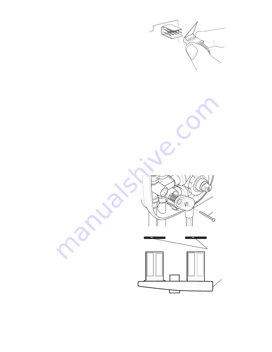
Remove the cover electrical
connection from the PCB by
gripping the sides of the connector
between two fingers and easing
the connector free by moving from
side to side.

3.5.

To replace the cover, reconnect
the cover electrical connector and

Orientation

refit the cover.  Secure the cover by tightening the three cover retaining
screws. Refit the  temperature control knob.

Note! 

Two lugs on the top of the connector are provided to ensure the correct

orientation.

4. Inlet Filter Cap, Cleaning – Removal and Installation

The following procedure can be applied for cleaning or renewing the inlet filter cap or
inlet filter cap ‘O’ seals.

Warning!

 Before proceeding turn off the electrical and water supplies. The electricity

supply must be turned off at the mains and, if applicable, the appropriate circuit fuse
removed. Mains electrical connections are exposed when the cover is removed.

4.1.

Remove the front cover as detailed
in "

Front Cover – Removal and

Installation

".

4.2.

Unscrew the retaining screw and
remove the filter cap.

Note!

 A small amount of trapped

water may drain from the manifold.

4.3.

Thoroughly clean both the inlet
filter meshes. Inspect the ‘O’ seals
and renew if required. Before
refitting the inlet filter cap lightly
grease ‘O’ seals with a silicone
based lubricant.

4.4.

Refit components in reverse order.

4.5.

Restore the water supplies and
check for any leaks.

Filter
Cap

Retaining
Screw

aaaaaaa

aaaaaaa

aaaaaaa

aaaaaaa

aaaaaaa

aaaaaaa

aaaaaaa

aaaaaaa

aaaaaaa

aaaaaaa

aaaaaaa

aaaaaaa

aaaaaaa

aaaaaaa

aaaaaaa

aaaaaaa

aaaaaaa

aaaaaaa

aaaaaaa

aaaaaaa

aaaaaaa

aaaaaaa

aaaaaaa

aaaaaaa

aaaaaaa

aaaaaaa

aaaaaaa

aaaaaaa

aaaaaaa

aaaaaaa

aaaaaaa

aaaaaaa

aaaaaaa

aaaaaaa

aaaaaaa

aaaaaaa

aaaaaaa

aaaaaaa

aaaaaaa

aaaaaaa

aaaaaaa

aaaaaaa

aaaaaaa

aaaaaaa

aaaaaaa

aaaaaaa

aaaaaaa

aaaaaaa

aaaaaaa

aaaaaaa

aaaaaaa

aaaaaaa

aaaaaaa

aaaaaaa

aaaaaaa

aaaaaaa

aaaaaaa

aaaaaaa

aaaaaaa

aaaaaaa

aaaaaaa

aaaaaaa

aaaaaaa

aaaaaaa

aaaaaaa

aaaaaaa

aaaaaaa

aaaaaaa

aaaaaaa

aaaaaaa

aaaaaaa

aaaaaaa

aaaaaaa

aaaaaaa

aaaaaaa

aaaaaaa

aaaaaaa

aaaaaaa

aaaaaaa

aaaaaaa

aaaaaaa

aaaaaaa

aaaaaaa

aaaaaaa

aaaaaaa

aaaaaaa

aaaaaaa

aaaaaaa

aaaaaaa

aaaaaaa

aaaaaaa

aaaaaaa

aaaaaaa

aaaaaaa

aaaaaaa

aaaaaaa

aaaaaaa

aaaaaaa

Filter Cap

Use a silicon
based lubricant
to grease the
'O' seals.

4.6.

Refit the cover and secure with the three cover retaining screws, refit the
temperature knob.

4.7.

Restore the electrical supply.

4.8.

Commission the Mira Extreme, refer to 

“Commissioning: General

Commissioning”

.

Summary of Contents for Extreme Thermostatic

Page 1: ...Therm ostatic THESE INSTRUCTIONS ARE TO BE LEFT WITH THE USER POWERSHOWER THERMOSTATIC UserGuide Installation TH ER M O STATIC...

Page 2: ...13 7 Installation Before You Start 14 ConfiguringInletSupplies 15 ShowerInstallation 17 8 Commissioning GeneralCommissioning 22 Adjustable Maximum Temperature Setting 23 Temperature Override Button D...

Page 3: ...n be disabled if required The product is fitted with a 15 mm dual entry push fit inlet manifold which allows pipe connections to the top bottom or rear of the power shower The inlet manifold also cont...

Page 4: ...DO NOT operate the Mira Extreme if water leaks from the unit maintenance will be required before the Mira Extreme can be safely used 1 7 DO NOT allow the Mira Extreme to be run dry 1 8 DO NOT fit any...

Page 5: ...5 2 The Electrical Contractors Association ECA England and Wales 2 5 3 The Electrical Contractors Association of Scotland ECAS 2 6 The plumbing installation must comply with Water Supply Regulations B...

Page 6: ...and to confirm that the parts are included 1 MiraExtreme 1 x Mira Extreme Thermostatic Power Shower 9 1 x Push Fit Release Tool 3 x Rubber Wall Plugs 3 x Fixing Screws 3 x Rubber Feet 4 x Case Inserts...

Page 7: ...7 Dimensions Section 4 All dimensions are nominal and in millimetres 310 95 117 80 66 28 20 210...

Page 8: ...n 1 C with a 10 C change in the hot or cold water supply 1 4 2 The sensor effects a shut down to seepage in approximately 2 seconds if the cold supply fails 1 4 3 Shut down to seepage is achieved even...

Page 9: ...to will also affect the perceived noise level solid walls will provide a quieter operation 2 Plumbing 2 1 Inlet 15 mm Push fit inlet manifold 2 2 Outlet 1 2 BSP to BS2779 3 Electrical 3 1 Appliance po...

Page 10: ...ded on the back of the case allow air to circulate and water to drain from behind the appliance 1 8 WhenfittingtheMiraExtremewithwallentryinletsupplies itisrecommended that the supply pipework is seal...

Page 11: ...the inlet pipework in an easily accessible position These valves will allow the water supply to be turned off quickly to the Mira Extreme for maintenance purposes 3 7 When using surface mounted inlet...

Page 12: ...red head of water x mm Required head of water x mm 15 mm Elbow No of Elbows x 55 No of Elbows x 55 3 11 Long pipe runs and excessive use of 90 elbows will significantly reduce the head available to su...

Page 13: ...s not suitable for the Mira Extreme Incorrect supply connections Cistern Other Hot Draw Offs Incorrect Installation Correct Installation 4 InstallationDiagrams To prevent operational difficulties the...

Page 14: ...leopening TheMiraExtremecansupporttop bottomorwallentryconfigurationsforboththewater and power supplies Choose the appropriate configuration for your installation Refer to Configuring Inlet Supplies f...

Page 15: ...the top bottom or back of the case For top and bottom entries a thinned section of the case covering the top or the bottom cable channel must be removed before the cable can be fitted Supply Pipework...

Page 16: ...peratureknob 2 2 Unscrewthethreecoverretaining screws sufficiently to remove the cover Note The cover retaining screws are captiveandneednotberemoved 2 3 Lowerthecovergently takingcare not to apply an...

Page 17: ...allow for the fitting and removal of the cover Ensure that when the hose retaining ring is placed on the lowest position on the slide bar there is a minimum distance of 25 mm between the handset and t...

Page 18: ...ooden blocks however thesemethodsoffixingarebeyond the scope of this guide Warning Ensure the marked fixing points are not inline with buried cables and pipes before drilling 3 7 Drill 9 5 mm holes an...

Page 19: ...ifold due to the water supply pressure 3 11 Ensure that the end of the supply pipework is cut squarely and free fromburrswhichcandamagethe inlet manifold seals Chamfer the end of the pipe to assist in...

Page 20: ...ed in the channel in the back of the case 3 15 Connectthelive neutralandearth conductorsoftheelectricalsupply cable to the terminal block The supply cable earth connector should be sleeved 3 16 To ref...

Page 21: ...the Mira Extreme The power shower will now require commissioning Refer to Commissioning General Commissioning and Commissioning Adjustable Maximum Temperature Setting 3 20 To install the shower fittin...

Page 22: ...of the appliance Ensurethehosewasher is fitted 1 3 Turnthewatersuppliesfullyonat the isolating valves Check that waterisnotleakingfromthebottom of the case 1 4 Switch on the electrical supply to the...

Page 23: ...se temperatures Note An adequate supply of hot water at least 12 C above the required temperature must be available for correct operation of the shower control Warning Resetting the temperature of the...

Page 24: ...Cooler Turn spindle clockwise 2 6 Press the Stop button to stop the waterflow 2 7 Refitthetemperaturehubwiththe piponthetemperaturehubaligned to the slot on the thermostatic cartridge Securewiththere...

Page 25: ...ng isrecommendedfortheyoung theelderly theinfirm oranyoneinexperienced in the correct operation of the controls Follow the instructions below to disable the temperature override button 3 1 Turn the te...

Page 26: ...utton to start low flow of water 1 1 Pushthelowerflowcontrolbutton to start the flow of water 1 2 Pressthecorrectflowcontrolknob toobtainthedesiredflowofwater 1 3 Turnthetemperaturecontrolknob inthedi...

Page 27: ...Adjustable MaximumTemperatureSetting Maximum shower ingtemperaturetoo hot Maximumtemperature incorrectly set Reset maximum temperature Re ferto Commissioning Adjustable MaximumTemperatureSetting Clean...

Page 28: ...ted in correctly Appliance sited above coldwaterstoragecis tern Plumbing system fault airlock Open valves Contact your installer Contact your installer The appliance is not suitable for negative head...

Page 29: ...cold tap Maximum shower temperaturetoohot Shower runs cold after 5 10 minutes Insufficiently sized pipework for both sys tems to be used to gether Insufficient storage of hot water in cylinder Showert...

Page 30: ...ult airlock Blocked spray plate Open valves Clean filters Refer to Maintenance Inlet Manifold Check Valve The appliance is not suitable for negative head installations Refer to Installation Requiremen...

Page 31: ...shing up detergent or soap solution and then wiped dry using a soft cloth 3 FrontCover RemovalandInstallation Warning Before proceeding turn off the electrical and water supplies The electricity suppl...

Page 32: ...spectthe O seals and renew if required Before refitting the inlet filter cap lightly grease O seals with a silicone basedlubricant 4 4 Refitcomponentsinreverseorder 4 5 Restore the water supplies and...

Page 33: ...ropriate circuit fuse removed Mains electrical connections are exposed when the cover is removed 5 1 Remove the front cover as detailed in Front Cover Removal and Installation 5 2 Disconnect the elect...

Page 34: ...et port of the manifold 5 9 Inspect inlet manifold valve interface seals and renew if required Note When refitting the inlet manifold lightlygreasesealswith a silicone based lubricant Inlet Manifold M...

Page 35: ...turn off the electrical and water supplies The electricity supply must be turned off at the mains and if applicable the appropriate circuit fuse removed Mains electrical connections are exposed when...

Page 36: ...ayout and connections to the motor pump assembly 7 4 Release the bottom securing clip on the transfer tube and lift the motor pump assembly and the mounting block clear of the case Note Liftupthefront...

Page 37: ...thewiringconnections to the solenoid coil 8 5 Unscrew the screw securing the solenoidvalveclampbracketwith aT10Torxscrewdriverandremove the bracket 8 6 Disconnectthewiringconnections to the motor Note...

Page 38: ...plies The electricity supply must be turned off at the mains and if applicable the appropriate circuit fuse removed Mains electrical connections are exposed when the cover is removed 9 1 Remove the fr...

Page 39: ...tions are exposed when the cover is removed Caution Disconnectwiringbypullingonlyonthebodyofthespadeconnectorandnot the wire itself 10 1 Follow instructions 9 1 to 9 5 in the Maintenance section to re...

Page 40: ...mponents identified C 453 14 Filter Cap Assembly 453 15 Seal Pack components identified D 453 17 Extreme Temperature Knob Assembly 453 23 Mixer Valve Body components identified E 453 24 Inserts Rubber...

Page 41: ...41 147 67 G 453 01 453 14 F A E A A 453 09 453 04 453 17 453 27 B E F B F F H A C D C D G F F E C G B C D F D 453 13 H H 2 SparePartsDiagram...

Page 42: ...Notes...

Page 43: ...Notes...

Page 44: ...ineer to visit If later the performance of your shower declines consult this manual toseewhethersimplehomemaintenanceisrequired PleasecallourCustomerServicestotalkthedifficultythrough request service...

Reviews: