background image

ing  the  metering  switch  S5.  Next  the 
brush  connects  the  orange-wire  contact 
to  ground  to  close  the  release switch  S3.

As  noted  during  the  troubleshooting, 

suspect  S5  if  pushing  the  release  button 
part way  fails  to turn  on  the  LED  display. 
Suspect S3 if  the shutter w o n 't  release at 
the  electronic  settings.  You  can  now 
clean  the  brush  contact  and  the  sw itch­

board  lands.

But,  if  you  remove  the  switches  for 

cleaning,  you'll  have to readjust the switch 
board.  Adjust  the  switch  timing  by  first 
loosening  the  tw o  screws  —  one  holding 

the  brush  and  one  holding  the  switch 
board,  Fig.  101.  Then  shift the  position  of 
the  switch  board  to  set  the  amount  of 
release-slide  movement  needed  to  close 
each  switch.

Check  the  metering  switch  S5  first. 

Connect an ohmmeter between the green 

wire and ground.  Then slowly depress the 

release  button.  When  the  release  slide 
moves down 0.4mm,  the metering switch 

should  close.  Your  ohmmeter  should 
then  show  direct  continuity  between  the 
green  wire  and  ground.

To  check  the  release  switch,  make  sure 

you've set the speed knob to an electronical­
ly controlled speed. Then connect your ohm­
meter between the orange wire and ground. 

The  release  switch  should  close  when  the 

release slide  moves down  1 mm.

Double-check  the  switch  timing  by  set­

ting  a  mechanical  speed  —  0  or  B.  The

release-slide  latch  now  moves  out  of  the 

path  of  the  release  slide.  As  the  brush 
starts to  rotate clockwise,  the release-slide 
latch  blocks  the  switch  arm,  Fig.  101.

The brush should still rotate far enough 

to  close  the  metering  switch.  However, 
the  release-slide  latch  should  block  the 
brush  rotation  before  the  release  switch 
closes.

So,  w ith  your  ohmmeter  connected 

between  the  orange  wire  and  ground, 
depress  the  release  button.  The  release 

switch should  not close  —  no matter how 
far  down  the  release  slide  moves.  Then 
check  the  metering  switch  between  the 

green  wire  and  ground.  The  metering 

switch  should  close  when  the  release 
slide  moves  down  0.4mm.

REMOVING  THE  FLEX  CIRCUIT

Other  than  for  replacement  purposes, 

there  aren't  too  many  reasons  to  remove 

the  flex  circuit.  The  complete  flex  circuit 
does  come as a  replacement  part  (flexible 
circuit  base  plate,  A  set  —  0841).  A 

replacement  flex  includes  the  RTV 

(shutter-speed)  resistor,  but  not  the 
diaphragm  resistor  or  the  SPD  board. 
There's also  an  exchange program.  If you 
send  in  the  old  flex  circuit,  you  can  get 

the  replacement  for  about  half  price.

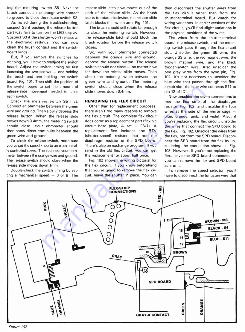
Fig.  102  shows  the  wiring  pictorial  for 

the  flex  circuit.  If  you  know  beforehand 

that  you're  going  to  remove  the  flex  cir­

cuit,  leave  the  shutter  in  place.  You  can

then  disconnect  the  shutter  wires  from 
the  flex  circuit  rather  than  from   the 

shutter-terminal  board.  But  watch  for 

wiring variations.  In earlier versions of the 

flex  circuit,  you'll  find  slight  variations  in 

the  physical  positions  of  the  wires.

The  wires  from  the  shutter-terminal 

board,  the  release switch,  and  the meter­
ing  switch  pass  through  the  flex-circuit 
slot.  Unsolder  the  green  S5  wire,  the 
orange  S3 wire,  the  red  magnet wire,  the 
brown  magnet  wire,  and  the  black 

trigger-switch  wire.  Also  unsolder  the 

tw o  gray  wires  from   the  sync  pin,  Fig.
102.  It's  not  necessary  to  unsolder  the 

blue  w ire  that  passes  through  the  flex- 
circuit slot;  the blue wire connects S11  to 
pin  12  of  IC1.

Now unsolder the seven connections to 

free  the  flex  strip  of  the  diaphragm 

resistor,  Fig.  102,  and  unsolder  the  four 

wires  at  the  side  of  the  mirror  cage  — 

blue,  orange,  pink,  and  violet.  Also,  if 
you're  replacing  the  flex  circuit,  unsolder 
the  wires  that  connect  the  SPD  board  to 
the flex,  Fig.  102.  Unsolder the wires from 
the flex,  not from  the SPD  board.  Discon­
nect  the  SPD  board  from   the  flex  by  un­
soldering  the  connection  shown  in  Fig.

103.  However,  if  you're  not  replacing  the 

flex,  leave  the  SPD  board  connected  — 
you  can  remove  the  flex  and  SPD  board 

as  a  unit.

To  remove  the  speed  selector,  you’ ll 

have to disconnect the tungsten wire that

FLEX-STRIP
C O N N E C TIO N S

B R O W N   -  M 3  

B L A C K   -  S4

SP D   B O A R D

G R A Y -X   C O N T A C T

Figure  102

Summary of Contents for XD-11

Page 1: ...Minolta XD 11 Repair Guide Figure IB OVERRANGE LED SHUTTER SPEED SCALE UNDERRANGE LED DIAPHRAGM WINDOW Figure 3 Figure 4...

Page 2: ...ong other innovations the XD 11 settled the debate over aperture preferred vs shutter speed preferred automation it gives you a choice between either mode To program the camera for automatic shutter s...

Page 3: ...perture sizes A combination magnet permanent magnet plus electromagnet limits the movement of the diaphragm closing lever As the diaphragm closing lever starts to move the permanent magnet holds its a...

Page 4: ...with its own batteries However you can connect a 3V DC power supply to the battery compartment Fig 8 Connect the positive power supply lead to the battery compartment terminal and connect the negativ...

Page 5: ...st be closed before the comparator output connects to the base of T6 S1 sits at the bottom of the camera Fig 11 When you cock the shutter S1 closes to connect the comparator to T6 S1 opens after the e...

Page 6: ...re may be a problem with the release switch or with the release circuit But if the transistor T6 is at fault you w on t have to go any fur ther You can make a final check on T6 by shorting between the...

Page 7: ...g 16 away from the M1 core toward the front of the camera The M1 ar mature now opens switch S7 Conse quently you should measure around 1 3V at the white wire connection Fig 15 The technique for holdin...

Page 8: ...manent magnet Fig 17 Dirt can prevent the core from magnetically hold ing the armature If cleaning doesn t do the job the per manent magnet may be defective Try pushing the armature of M2 away from th...

Page 9: ...D IAPH RAG M CONTROL IC2 SHUTTER RELEASE LOCK DRIVER FOR LEDs IC1 D IAPHRAG M CONTROL PHOTOCELL AMPLIFIER SPEED CONTROL OUTPUT LIGHT LEVEL FILM SPEED Figure 18 Actual schematic Figure 19...

Page 10: ...ting provides the in put voltage to one input of the com parator the combination of the film speed setting and the photocell output provides the voltage at the other input If input 1 in Fig 19 is less...

Page 11: ...sassembly Remove the speed knob and note the loose release pin The release pin closes the switches for the metering and release functions You can completely remove the camera back by depressing the hi...

Page 12: ...ring Then rotate the wind lever in a counterclockwise direction as you seat it over the wind shaft The upper coil of the wind lever return spring sometimes sneaks under the wind lever If that hap pens...

Page 13: ...e the film speed dial Why With the film speed dial remov ed the film speed brush doesn t make firm contact with the resistor ring Fig 31 The camera then exhibits the symp toms of an open film speed re...

Page 14: ...ask lever pulls the mask over the window for the shutter speed indication Remember the shutter speed setting has no meaning in the A mode The spring loaded scale to the front of the pentaprism provide...

Page 15: ...memory capa citor can continue changing as long as the memory switch Fig 36 remains clos ed Fig 33 points out the memory switch in the camera Just before the mirror starts to rise the insulated lever...

Page 16: ...ansistor charges the timing capacitor With a larger more positive base voltage the transistor con ducts harder it then charges the timing capacitor more quickly However if there s no voltage across th...

Page 17: ...the shutter to deliver only its fastest speed Suspect a poor ground connection if you measure a voltage at the red electromagnet lead when you par tially depress the release button If you measure arou...

Page 18: ...l hang open If the trigger switch fails to close or makes poor con tact you w on t be able to bring in your shutter speed adjustments especially the fast speeds Erratic shutter speeds may also result...

Page 19: ...parator provides the switch for the closing curtain electromagnet M3 When the comparator output at pin 16 drops low current flows through M3 to hold open the shutter The voltage at pin 16 goes high to...

Page 20: ...Figure 41...

Page 21: ...board Finally take out the four front plate screws Notice the position of the one slotted screw the locating screw in the upper wind side corner You can now separate the front plate m irror cage assem...

Page 22: ...escribe a special tool for adjusting the LED readout a dummy camera body which has a special cutout over the variable resistors But according to Minolta the dummy camera body isn t available You can t...

Page 23: ......

Page 24: ...round 0 6V despite changes in current So with two diodes in series the voltage at pin 7 should remain constant at approximately 1 2V The filter capacitor C1 helps maintain the constant reference volta...

Page 25: ...Figure 52...

Page 26: ...istor labeled R47 in Fig 52 The f 22 lens moves the brush to the third resistance path here the S12 brush connects pin 9 of IC2 directly to positive battery Fig 52 With the f 32 lens the brush moves o...

Page 27: ...he overexposure LED to re main on You can use another voltage check to test the diaphragm resistor after removing the top cover Measure the volt age between ground and the AV contact Fig 54 you should...

Page 28: ...of the LEDs will turn on W ith the front plate m irror cage assembly removed you have a good view of S7 Fig 60 Fig 60 shows the mirror cage in the charged position The M1 ar mature now sits in contact...

Page 29: ......

Page 30: ...have to stop down as far in bringing the pin 8 voltage to the pin 11 voltage At the X B and 0 settings the shutter speed brush moves to the ground land shown just below the RTV resistor in Fig 63 Pin...

Page 31: ...ve for transistor 1 Fig 64 The timing capacitor then charges more quickly You can then check the shutter speed resistor RTV by measuring the voltage to pin 20 of IC1 in the M mode Again the voltage sh...

Page 32: ...14 of IC1 ground and the negative lead of C3 Fig 55 The large resistor has no effect on the normal operation However it allows the timing capacitor to eventually charge and close the shutter You may...

Page 33: ...ixed resistor R56 as shown in Fig 69 Depress the release button part way to measure the voltage You should get a reading of 180mv 0 180V 2mv If not make the adjust ment using Rx7 Turning the wiper of...

Page 34: ...ond and the diaphragm to f 16 With the film speed dial set to ASA 100 expose the lens to a light level of EV 9 Now measure the voltage between the common S11 path Fig 66 and ground Record your voltage...

Page 35: ...y find that the shutter occasionally jams the closing blade doesn t quite complete its release movement Then by pushing down the closing blade from the back you may be able to get the shutter to opera...

Page 36: ...Figure 73 WASHERS Figure 75 Figure 77 Figure 74 Closing blade set Part 2005 0712 01 Figure 76 Opening blade set Part 2005 0713 01...

Page 37: ...out the three shutter retaining screws Then lift the shutter far enough from the mirror ARM CLOSING BLADE Figure 79 First section o f opening blade in position Figure 80 cage to reach the wires which...

Page 38: ...closing blade push the bulb lever out of engage ment with the armature from left to right in Fig 84 The spring loaded armature then moves away from the electromagnet and strikes the closing blade lat...

Page 39: ...e the armature But another lever the mechanical speed latch holds the armature to provide the full aperture speed The mechanical speed latch sits just under the bulb lever Fig 86 When the opening blad...

Page 40: ...reasing the spring tension by turning the spring hooking tab counterclockwise causes the timing cam to rotate faster The result A significant change in the fast speeds But don t use the spring hooking...

Page 41: ...re Fig 89 It s now up to the electromagnet the bulb lever or the mechanical speed latch to hold the ar mature and prevent the closing blade from releasing Also the ridge on the timing cam drives the t...

Page 42: ...h that you don t lift up the blade driving levers If you do the pins on the other sides of the blade driving levers will come out of the slots in the blade sets Then if the in dividual blades shift in...

Page 43: ...circuit for adjusting the trig ger switch Just connect the timing cir cuit to the shutter s lead wires as shown Figure 99 in Fig 98 There s only one problem you disconnect the shutter leads to remove...

Page 44: ...agnet In Fig 100 we ve provided a variable resistor adjust ment to establish the reference voltage at the noninverting input of the comparator Use the variable resistor to adjust the tim ing circuit f...

Page 45: ...he metering switch should close when the release slide moves down 0 4mm REMOVING THE FLEX CIRCUIT Other than for replacement purposes there aren t too many reasons to remove the flex circuit The compl...

Page 46: ...tially depressed It s also possible to check the individual LEDs without removing the flex circuit completely Fig 104 points out the hole that receives the ground screw Connect a jumper between the gr...

Page 47: ...resulting in a shorter delay between the closing of the release switch and the opening of the memory switch The time delay assures that the dia phragm reaches the taking aperture before the memory sw...

Page 48: ...mir ror cage Remember though that remov ing the combination magnets requires that you readjust their positions on reassembly You can now see the diaphragm control parts The mirror tensioning lever mo...

Page 49: ...se the eccentric if the self timer fails to pull down the release slide far enough to release the shutter TIMING THE SPEED SELECTOR On reassembly it s possible to replace the speed selector 180 out of...

Page 50: ...tension on the spring the scale would definitely break After you connect one end of the tung sten wire hold the other end as shown in Fig 115 Now let go of the spring loaded pulley and allow the sprin...

Page 51: ...ut the two wind seat screws Fig 119 Then lift out the wind seat Watch for a loose endplay spacer on the top of the wind shaft Fig 120 not all cameras use the endplay spacer Also if you removed the win...

Page 52: ...e sprocket gear at the bottom of the body casting Watch for a washer on top of the sprocket gear You can now remove the take up spool from the back of the body casting Fig 123 The take up spool has th...

Page 53: ...roper position of the notch Seat the two plastic gears on the base plate Then insert the counter ac tuator into the hole in the back sensing lever Rotate the counter actuator to the position shown in...

Page 54: ...counter gear Fig 125 If the counter actuator doesn t align with the tooth slot and instead comes against one of the gear teeth you ll see the counter dial shift in position as you close the camera bac...

Page 55: ...lastic gears in the Seiko aren t nylon they re Delrin the toughest of plastics The Delrin parts never seem to break Although the Seiko holds up under most types of abuse there s one mis treatment it c...

Page 56: ...brown and red magnet leads Fig 39 shorted 3 H IC defective Check the voltage at pin 10 Fig 51 You should get 3V when the shutter releases 4 IC1 defective Check the voltage at the brown electromagnet...

Reviews: