Pin 19, Fig. 65, provides the charging
voltage for the memory capacitor. The
voltage at pin 19 should go more positive
as you set faster shutter speeds on
manual or as you increase the light level
on automatic. The same voltage appears
at pin 10. Pin 10 couples the memorized
reference voltage from the memory
capacitor to the current-control circuit
that charges the timing capacitor.
A t pin 9, you should see a OV signal un
til you release the shutter. The voltage
then swings positive to negative (OV) to
turn on T13.
You can check switching actions at the
other pins. For example, pin 12 connects
to the trigger switch. W ith the shutter
cocked, you should measure OV at pin 12;
the closed trigger switch then connects
pin 12 to ground. However, you should
measure around 1,3V during the exposure
when the trigger switch opens. W hat if
you don't? If the voltage stays at OV,
suspect a problem w ith the trigger
switch.
Another switch — S11 of the mode
switch — connects to pin 11. If the shut
ter delivers only the mechanical exposure
in all modes, you might check the pin 11
voltage. You should see the voltage
change as you move the mode switch
from the S position to the A position. If
not, suspect poor contact in S11.
As another example, S9 of the mode
switch connects to pin 20. Here, you
should see a voltage change as you go
from the M mode to the A mode. Poor
contact in S9 could cause the shutter to
hang open in all modes. Fig. 66 points out
the mode-switch paths that correspond
to S8, S9, S11, and S13.
MODIFICATION TO THE
TIM IN G CIRCUIT
You may recall the symptom of a
shorted memory capacitor C2 — the shut
ter hangs open on all modes. W ith no
voltage across the memory capacitor,
transistor #1, Fig. 64, has no base drive.
Consequently, it can't charge the timing
capacitor. The same symptom may result
from poor contact in the memory switch.
Similarly, under very low light condi
tions, there's a low voltage across the
memory capacitor. If you operate the
camera at one of the automatic settings in
complete darkness, the shutter hangs
open until the batteries die. You can, of
course, remove the batteries to close the
shutter. But Minolta discovered that
owners were going through batteries by
letting their shutters hang open.
A t the current price of silver-oxide bat
teries, Minolta felt the problem deserved
a modification — a modification that
allows the timing capacitor C3 to event
ually charge. Minolta suggests adding a
large-value resistor — 50 megohms — be
tween pin 14 of IC1 (ground) and the
negative lead of C3, Fig. 55.
The large resistor has no effect on the
normal operation. However, it allows the
timing capacitor to eventually charge and
close the shutter. You may have some
trouble locating a 50M resistor that's
small enough in size. Fortunately, Minolta
does supply the resistor through their
parts department;
it's part number
9431-1078-31.
REPAIRING AND ADJUSTING
THE COMBINATION MAGNETS
W e've already described the trouble
shooting steps to detect an open coil in
either M1 or M2, Fig. 63. Remember, an
open M1 coil prevents the mirror from
releasing. If M2 has an open coil, the
diaphragm always stops down fully in the
S mode.
However, you may also encounter
mechanical problems w ith the combina
tion magnets. Dirt causes one such prob
lem. For example, dirt between the M1 ar
mature and the magnet core prevents the
magnetic attraction. As a result, the mir
ror releases as soon as you complete the
cocking stroke.
Dirt can cause a similar problem w ith
the M2 magnet. If M2 fails to hold its ar
mature, the diaphragm can't stop down.
The armature arrests the ratchet gear as
soon as the diaphragm starts to close.
Minolta has improved both the M1
magnet and the M2 magnet to minimize
the dirt problem. In the newer designs,
the armature moves a rod w ithin a hole.
The hole serves to seal both the armature
and the core from dirt.
Incorrect adjustments cause similar
problems. But you normally don 't have to
adjust the magnets — not unless you've
replaced either M1 or M2. If you replace a
magnet, you'll have to adjust its position.
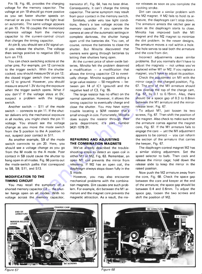
Check the adjustment on M1 w ith the
mirror cage in the charged position, Fig.
67. The end of the M1 armature should
now overlap the top of the charge cam,
Fig. 67, by 0.1 to 0.15mm. Also, there
should be a space gap of 0.3 to 0.8mm
between the M1 armature and the mirror-
release lever, Fig. 67.
To adjust M1, just loosen its tw o
screws, Fig. 67. Then shift the position of
the magnet. Also check to make sure that
the armature comes against the magnet
core, Fig. 67. If the M1 armature fails to
engage the core — yet the M1 adjustment
appears to be correct — you can reform
the section of the armature that carries
the keeper, Fig. 67.
The diaphragm-control magnet M2 has
a similar sliding adjustment. Set the
speed selector to bulb. Then cock and
release the mirror cage; hold down the
release slide to keep the mirror in the
raised position.
Now push the M2 armature away from
the core, Fig. 68. Check the space gap
between the core and keeper at the end
of the armature; the space gap should be
between 0.4 and 0.6mm. To adjust the
space gap, loosen the tw o screws and
shift the position of M2.
Figure 67
Figure 68


