cuit takes its light reading through the
largest aperture — and the exposure-
control circuit takes its light reading
through the stopped-down aperture — the
two systems can disagree. For example,
suppose there’s a problem with the
diaphragm resistor. Although the LED in
dication would then be incorrect, the shut
ter would still provide the proper exposure.
You can get a better idea of the tw o
separate actions if you operate the
camera on " A " w ith the lens removed.
Try rotating the diaphragm-metering ring
until the LED display indicates a slow
shutter speed. Then release the shutter.
You'll find that the shutter delivers an ex
posure time that's much faster than the
readout indicates. Why? You tricked the
readout into thinking you'd set a small
aperture. But the exposure-control circuit
knew better.
A t the manually calibrated settings, the
meter readout still tells you the proper
shutter speed for the light conditions.
However, the shutter-speed setting —
rather than the op amp — controls the
voltage across the memory capacitor. As
you set faster shutter speeds, the voltage
across the memory capacitor increases.
Earlier, we mentioned the symptom
when there's poor contact at one side of
the mode switch — the shutter hangs
open at all functions. You can see w hy in
Fig. 36. If the mode switch fails to make
good contact, the memory capacitor
y c a n 't charge. Then, since the shutter
thinks you're shooting in total darkness, it
hangs open.
A defective memory capacitor or poor
contact in the memory switch, Fig. 36,
results in the same malfunction. In fact,
any condition which prevents a reference
voltage causes the shutter to hang open.
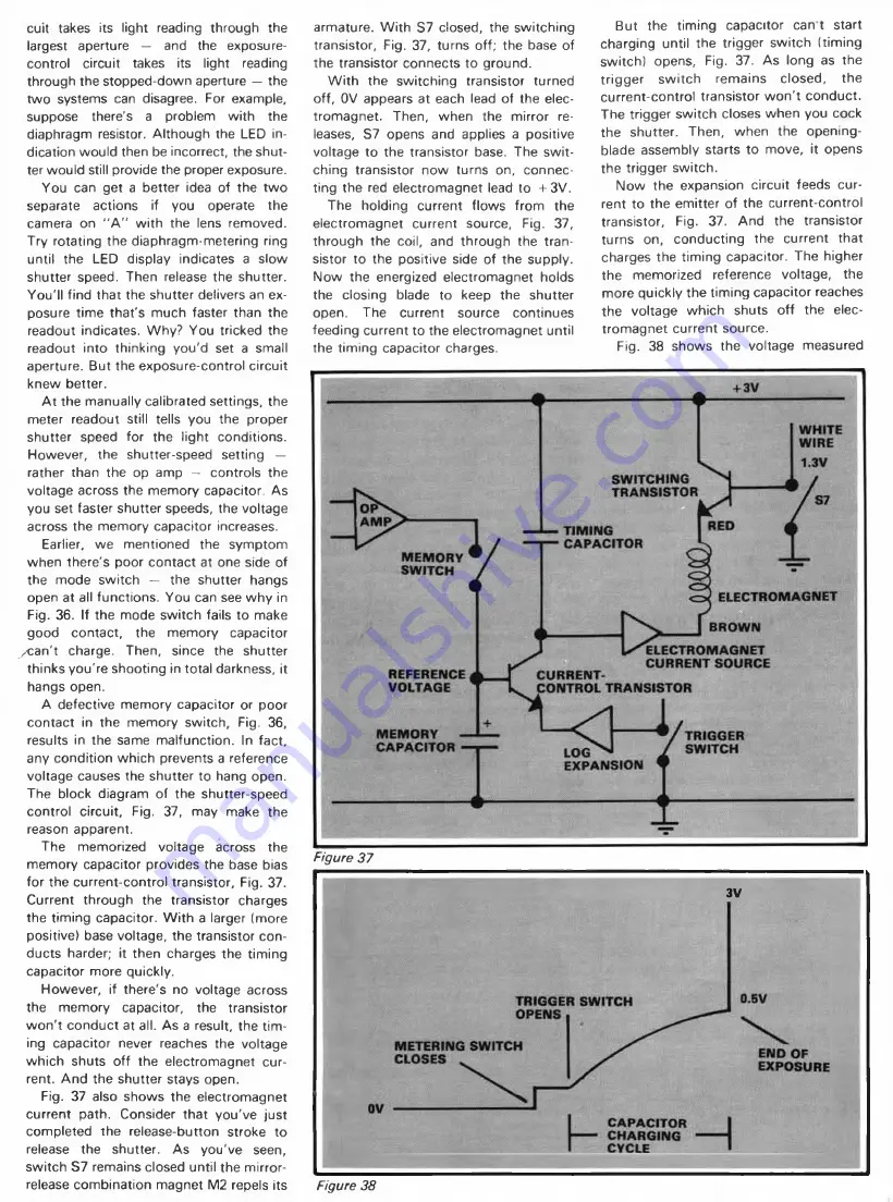
The block diagram of the shutter-speed
control circuit, Fig. 37, may make the
reason apparent.
The memorized voltage across the
memory capacitor provides the base bias
for the current-control transistor, Fig. 37.
Current through the transistor charges
the timing capacitor. W ith a larger (more
positive) base voltage, the transistor con
ducts harder; it then charges the timing
capacitor more quickly.
However, if there's no voltage across
the memory capacitor, the transistor
w o n 't conduct at all. As a result, the tim
ing capacitor never reaches the voltage
which shuts off the electromagnet cur
rent. And the shutter stays open.
Fig. 37 also shows the electromagnet
current path. Consider that you've just
completed the release-button stroke to
release the shutter. As you've seen,
switch S7 remains closed until the mirror-
release combination magnet M2 repels its
armature. W ith S7 closed, the switching
transistor. Fig. 37, turns off; the base of
the transistor connects to ground.
W ith the switching transistor turned
off, OV appears at each lead of the elec
tromagnet. Then, when the mirror re
leases, S7 opens and applies a positive
voltage to the transistor base. The sw it
ching transistor now turns on, connec
ting the red electromagnet lead to + 3V.
The holding current flows from the
electromagnet current source, Fig. 37,
through the coil, and through the tran
sistor to the positive side of the supply.
Now the energized electromagnet holds
the closing blade to keep the shutter
open. The current source continues
feeding current to the electromagnet until
the timing capacitor charges.
Figure 37
But the timing capacitor can t start
charging until the trigger switch (timing
switch) opens. Fig. 37. As long as the
trigger sw itch remains closed,
the
current-control transistor w o n 't conduct.
The trigger switch closes when you cock
the shutter. Then, when the opening-
blade assembly starts to move, it opens
the trigger switch.
Now the expansion circuit feeds cur
rent to the emitter of the current-control
transistor. Fig. 37. And the transistor
turns on, conducting the current that
charges the timing capacitor. The higher
the memorized reference voltage, the
more quickly the timing capacitor reaches
the voltage which shuts o ff the elec
tromagnet current source.
Fig. 38 shows the voltage measured
3V
Figure 38


