background image

9  |  minnkotamotors.com

©2022 Johnson Outdoors Marine Electronics, Inc.

i. 

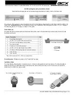
Slide the Base Extrusion into place on the Screws 
that were just installed. The Base Extrusion should 
slide between the Top Plate and the Clipped 
Washers. Hold the Clipped Washers up on the 
Screws so that the Clipped Washers will sit on top of 
the Base Extrusion.

j. 

With the motor in place, secure each Screw with a 
Nylock Nut and tighten with a 7/16" Box End or Open 
End Wrench. Make sure all hardware is secure. 

Nylock 

Nylock 

Nut

Nut

Base 

Base 

Extrusion

Extrusion

Top Plate

Top Plate

Clipped Washer

Clipped Washer

5j

5

k.  Move to the Damper side of the Ulterra to install the 

remaining hardware. Ensure that the Mounting Holes 
in the Base Extrusion are aligned with the Mounting 
Holes in the Top Plate. 

l. 

Take two each of the Hex Head Cap Screws  
(Item #14), Clipped Washers (Part #2201725) and 
Nylock Nuts (Item #16). Insert the Screws from the 
bottom up, through the Top Plate and into the Base 
Extrusion. When installing the Screws, use only 
the outermost mounting holes on the Top Plate. 
The center mounting hole will not be used. Place a 
Clipped Washer on each Screw, positioned so that 
the flat side of the Washer faces towards the Base 
Extrusion. Secure each Screw with a Nylock Nut and 
tighten with a 7/16” Box End or Open End Wrench. 
Make sure all hardware is secure. 

Mounting Holes

Mounting Holes

Base 

Base 

Extrusion

Extrusion

Top Plate

Top Plate

Hex Head 

Hex Head 

Cap Screw

Cap Screw

Clipped  

Clipped  

Washer

Washer

Nylock 

Nylock 

Nut

Nut

CAUTION

Use extra care to avoid pinching and damaging the 
sensor wires that run alongside the Base Extrusion 
when installing and tightening the mounting hardware.

6

6k

6l

ITEM(S) NEEDED

#16 x 2

#14 x 2

Base 

Base 

Extrusion

Extrusion

Top Plate

Top Plate

Clipped Washer

Clipped Washer

5i

Summary of Contents for 1854035

Page 1: ...to the centerline or keel of the boat as possible The motor must not encounter any obstructions as it is lowered into the water or raised into the boat when stowed and deployed Make sure the motor re...

Page 2: ...e Gunwale and the Shaft 2 For Ulterra Motors Position the mount so the Slot in the Base Extrusion is positioned beyond the gunwale of the boat For proper clearance the entire Slot must be visible beyo...

Page 3: ...lates completely apart and set the Bottom Plate aside The Top Plate will be installed first d On the Top Plate take note of the Padlock Slot on the side of the Plate near the Socket Head Cap Screw Whe...

Page 4: ...he four Sideplate screws using a 3 Phillips Screwdriver Two of these screws will be located on each side of the mount NOTICE A motor may weigh up to 65lbs Minn Kota recommends having a second person h...

Page 5: ...ideplate back into its correct position on the Base Extrusion j Replace the four sideplate screws using a 3 Phillips Screwdriver Two of these screws will be located on each side of the mount Right Sid...

Page 6: ...ws from the bottom up through the Top Plate and into the DeckHand 40 Base and Davit Secure each Screw with a Nylock Nut and tighten with a 7 16 Box End or Open End Wrench Make sure all hardware is sec...

Page 7: ...Deployed Deployed Stowed Stowed a Place the mount on an elevated level surface such as a workbench or the tailgate of a pickup The motor should be in the stowed position NOTICE This installation requi...

Page 8: ...se Base Extrusion Extrusion Inboard Inboard Padlock Slot Padlock Slot Hex Head Hex Head Cap Screw Cap Screw f Start with the right side of the Ulterra where the Power Tilt is located There are three M...

Page 9: ...he Hex Head Cap Screws Item 14 Clipped Washers Part 2201725 and Nylock Nuts Item 16 Insert the Screws from the bottom up through the Top Plate and into the Base Extrusion When installing the Screws us...

Page 10: ...Bottom Plate Item 4 Align the Plates and secure with the Lock Washer and Tension Screw Knob b Place the motor with the Quick Release Bracket attached as close to the centerline or keel of the boat as...

Page 11: ...d Markings Markings Lock Washer Lock Washer Tension Tension Screw Knob Screw Knob Bottom Bottom Plate Plate Bow Bow Markings Markings Inboard Inboard Inboard Inboard Top Plate Top Plate 2c 2d 2c 2 e R...

Page 12: ...Plate over the drilled holes Ensure that the U Shape points inboard Insert a Mounting Bolt Item 18 into each of the four drilled locations The Bolts should pass from the top down through the Bottom Pl...

Page 13: ...teur ne doit rencontrer aucune obstruction lorsqu il est abaiss dans l eau ou mont dans le bateau pour arrimage ou d ploiement Assurez vous que le repose moteur est positionn assez loin du bord du bat...

Page 14: ...i re ce que la fente de l extrusion de la base soit positionn e au del du plat bord du bateau Le d gagement est appropri lorsque la totalit de la fente est visible au del du plat bord Lorsque le moteu...

Page 15: ...c t La plaque sup rieure sera install e en premier d Sur la plaque sup rieure notez la fente pour cadenas sur le c t de la plaque pr s de la vis t te creuse Lorsque la plaque sup rieure est install e...

Page 16: ...utilisant un tournevis cruciforme n 3 Deux de ces vis seront situ es de chaque c t du support AVIS Un moteur peut peser jusqu 65 lb 29 5 kg Minn Kota recommande d obtenir l aide d une deuxi me person...

Page 17: ...ale ou une cl ouverte de 7 16 po 11 1 mm Assurez vous que toute la quincaillerie est bien fix e 14 x 4 2 x 1 16 x 4 Plaque Plaque sup rieure sup rieure Trous de Trous de montage montage Trous de Trous...

Page 18: ...et dans la base et le bossoir du DeckHand 40 Fixez chaque vis avec un crou Nylock et serrez avec une cl polygonale ou une cl ouverte de 7 16 po 11 1 mm Assurez vous que toute la quincaillerie est bie...

Page 19: ...n cessaires AVIS Un moteur peut peser jusqu 65 lb 29 5 kg Minn Kota recommande d obtenir l aide d une deuxi me personne pour l installation b Retirez les quatre vis de la plaque lat rale en utilisant...

Page 20: ...aque Plaque sup rieure sup rieure Extrusion Extrusion de la base de la base En bord En bord Fente pour Fente pour cadenas cadenas Vis t te creuse Vis t te creuse hexagonale hexagonale f Commencez par...

Page 21: ...ondelles taill es pi ce n 2201725 et deux crous Nylock article n 16 Ins rez les vis de bas en haut travers la plaque sup rieure et dans l extrusion de la base Lorsque vous installez les vis utilisez u...

Page 22: ...nt glisser la plaque sup rieure et le moteur sur la plaque inf rieure article n 4 Enlignez les plaques et fixez les avec la rondelle de blocage et le bouton vis de tension b Placez le moteur avec le s...

Page 23: ...de Rondelle de blocage blocage Bouton vis Bouton vis de tension de tension Plaque Plaque inf rieure inf rieure Proue Proue Marques Marques En bord En bord En bord En bord Plaque Plaque sup rieure sup...

Page 24: ...Ins rez un boulon de montage article n 18 dans chacun des quatre emplacements perc s Les boulons doivent passer de haut en bas travers la plaque inf rieure et dans le pont du bateau h Placez une rond...

Reviews: