background image


miniDSP Ltd, Hong Kong / 

www.minidsp.com

 / Features and specifications subject to change without prior notice


1


P

RODUCT 

O

VERVIEW


Thank you for purchasing a 

NanoAVR DL

 HDMI audio processor powered by Dirac Live®, the world’s premier 

room correction solution. We are delighted to offer you this software and hardware combination, the fruit of 
extensive research and development and years of experience in sound system tuning. 

The 

nanoAVR DL

 is a 2-input HDMI 1.4a switch combined with a sophisticated digital audio signal processor 

(DSP) running the Dirac Live® room correction algorithm. The onboard floating-point SHARC processor allows full 
time and phase correction of a 7.1 home theater or multichannel audio system using linear PCM (LPCM) audio. 

The nanoAVR DL is one of the products in the miniDSP 

Home Theater Series

 of audio processors. Deploying a 

nanoAVR DL

 processor in your home theater system will: 


Improve imaging and immersion 


Improve clarity of music and dialog 


Produce a tighter bass 


Reduce listening fatigue 


Remove resonances and room modes 


Reduce early reflections 

1.1


T

YPICAL SYSTEM CONFIGURATION


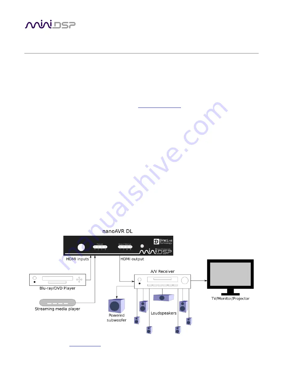
The nanoAVR DL typically connects between an HDMI source such as a Blu-ray player and an A/V receiver or 
processor. Two HDMI sources can be connected to the nanoAVR DL. Audio from the selected HDMI input is 
processed by the Dirac Live® algorithm and passed to the output. Video from the selected input is switched 
directly to the output, with no processing applied to the video signal. 


Summary of Contents for NANOAVR DL

Page 1: ...miniDSP Ltd Hong Kong www minidsp com Features and specifications subject to change without prior notice 1 NANOAVR DL 8 CHANNEL HDMI AUDIO PROCESSOR WITH DIRAC LIVE TECHNOLOGY User Manual...

Page 2: ...miniDSP Ltd Hong Kong www minidsp com Features and specifications subject to change without prior notice 2 Revision history Revision Description Date 1 0 Initial public release 4 December 2014...

Page 3: ...stallation 11 2 1 3 License activation 12 2 1 4 License validation 13 2 2 Hardware connectivity 14 2 2 1 HDMI input and output 14 2 2 2 Ethernet 14 2 2 3 DC Power 15 2 2 4 USB 15 3 Acoustic Measuremen...

Page 4: ...et curves 31 4 3 Generating correction filters 32 4 4 Downloading and managing filter sets 33 5 Using the NanoAVR DL HDMI audio processor 34 5 1 Status indicators 34 5 2 Front panel controls 34 5 3 In...

Page 5: ...otential to cause damage to your audio system Please also note that many of the questions we receive at the technical support department are already answered in this User Manual and in the online appl...

Page 6: ...e party responsible for compliance could void the user s authority to operate the equipment CE MARK STATEMENT The nanoAVR DL has passed the test performed according to European Standard EN 55022 Class...

Page 7: ...phase correction of a 7 1 home theater or multichannel audio system using linear PCM LPCM audio The nanoAVR DL is one of the products in the miniDSP Home Theater Series of audio processors Deploying a...

Page 8: ...d to imprecisely as frequency response In contrast to fully automated systems Dirac Live corrects the magnitude response towards a user adjustable target response The target response takes account of...

Page 9: ...heir impulse response characteristics neither can make a desired change to the magnitude response independently of controlling the impulse response In some cases they may even make things worse Mixed...

Page 10: ...of acoustic measurements using the Dirac Live Calibration Tool For miniDSP program to capture the acoustic behavior of your speakers and room See Section 3 Acoustic Measurement 3 Generate the digital...

Page 11: ...r has shipped your installation software downloads will be available at the User Downloads section of the miniDSP website under the NanoAVR heading http www minidsp com userdownloads There are two pro...

Page 12: ...ct button It will change to a green tick 3 Click on Get Activation Serial Number The program will get your unique serial number from the connected nanoAVR DL and display it as shown on the right below...

Page 13: ...own at left in step 4 above 3 If you purchase more than one NanoAVR DL or Dirac Series processor each will need to be activated with its unique serial number Use the form shown on the right in step 4...

Page 14: ...er sources may include media streaming devices and computers with an HDMI port The output connector will be connected to an HDMI input on an A V receiver or processor Ensure that your HDMI sources are...

Page 15: ...bilities of each device We recommend that for at least the first time the system is powered up equipment be powered on in this order TV AVR nanoAVR DL source player 2 2 4 USB To configure the nanoAVR...

Page 16: ...oudspeaker and subwoofer positioning should be optimized In particular the location of the subwoofer within the room will have a large impact on the smoothness of bass response With Dirac Live you hav...

Page 17: ...o a USB port on the computer 2 Connect the supplied USB type A to mini type B cable from the UMIK 1 to a USB port on the computer Place the UMIK 1 microphone into a microphone stand and position the c...

Page 18: ...us here Screen selection tabs Each tab selects the information shown in the main display area These are generally worked through in order from top to bottom This section covers the first four tabs the...

Page 19: ...ation For home theater use usually 5 1 or 7 1 will be selected Test signal playback device Preset to nanoAVR DL This will ensure that test signals are sent into your audio system via the NanoAVR DL pr...

Page 20: ...rophone is individually calibrated to ensure accuracy To download the unique calibration file for your microphone go to the UMIK 1 page and enter your microphone s serial number It is in the form xxx...

Page 21: ...voice would have to be raised to converse with someone sitting next to you Increase the Input gain slider until the blue bar on the level meter reaches up into the green section Click again on the Te...

Page 22: ...miniDSP Ltd Hong Kong www minidsp com Features and specifications subject to change without prior notice 22 3 4 RUNNING THE MEASUREMENTS Measurements are performed on the Measurements tab...

Page 23: ...d listening environment with dots marking the recommended microphone locations Completed measurements are shown in green while the next measurement to be done is highlighted in yellow and has a red ar...

Page 24: ...er then the right and so on through all channels including the subwoofer Finally the frequency sweep plays through the left speaker again While the measurement proceeds the time domain response graph...

Page 25: ...is recalculating parameters To redo a measurement delete it move the microphone to the appropriate location and click on Start Note if more than one measurement is deleted the marker will move to the...

Page 26: ...onses These plots are shown in light blue Avg spectrum after The predicted average magnitude response after correction These plots are shown in green and can only be viewed after filters have been gen...

Page 27: ...rements The predicted responses after correction can be viewed after filters are generated with the Optimize button see Generating correction filters below To return to the magnitude response click on...

Page 28: ...ve as this will make it easier to experiment with target curves Once you are up and running with filter sets you can experiment with different target curves for different channel groups The response g...

Page 29: ...rve You can edit the target curve to set any desired magnitude response see Guidelines for target curve design below This is done with the use of anchor points shown as orange dots on the curve Drag a...

Page 30: ...the system so it is important that you experiment with different target curves to find the optimum If you initially don t achieve a satisfactory result please ensure that you have spread your measure...

Page 31: ...ay be helpful to adjust the target curve to follow dips in the magnitude response This can occur where for example the listening area is very close to the speakers and the measurements exhibit a dip c...

Page 32: ...speed of your computer When the algorithm completes the predicted average magnitude response will be shown in green The predicted impulse response can be viewed by clicking on the Impulse button The D...

Page 33: ...onto an empty slot To remove a filter set click on its name oriented vertically drag it from the slot and drop it on the trashcan icon at the top right To load a filter set into a slot that already ha...

Page 34: ...nly 5 1 STATUS INDICATORS The current status of the nanoAVR DL is indicated by a set of LEDs Preset Indicates the currently selected filter set 1 through 4 Input Indicates the currently selected HDMI...

Page 35: ...one of the function buttons in the IR Learning box Master Mute Volume Up and so on Then point your remote at the processor and click on the button that you want to use for that function A dialog will...

Page 36: ...hernet router or switch The diagram below illustrates a typical case where the Ethernet router also acts as a wireless base station and is in turn connected to an ADSL cable modem It is also common fo...

Page 37: ...ate 192kHz DSP internal processing path 48 kHz Audio processing 32 bit floating point processor Video support Video pass through of selected source i e no video processing 36 bit 3D support HDCP embed...

Page 38: ...the USB cable to the nanoAVR DL is firmly connected b Check that you do not have any other program running that is attempting to communicate with the nanoAVR DL such as the nanoAVR DL utility program...

Page 39: ...that each unit TV AVR nanoAVR has the correct HDMI input selected d Power cycle the complete system Turn off all equipment and after waiting a minute turn equipment on again in the following order TV...

Page 40: ...n the installer Then follow the steps below Note that the firmware upgrade tool is as of publication of this User Manual available on Windows only 1 Unplug DC power from the nanoAVR DL 2 Connect the n...

Page 41: ...utton The status display should change to show that the program has connected 8 Click the Load Hex File button Browse to the hex firmware file located in the unzipped download folder and select it Thi...

Page 42: ...he nanoAVR DL 11 Click the Disconnect button 12 Close the PIC32UBL application Provided firmware update was successful you can now continue to use the nanoAVR DL as before 6 4 OBTAINING SUPPORT 1 Chec...

Reviews: