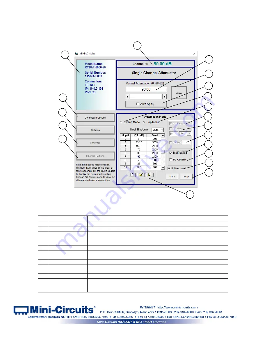
3.2
Operating the Attenuator with the GUI Program
3.2.1
Once you’ve selected the control method to use,
the main screen of the
GUI program will appear.
3.2.2
Manual Mode functions:
#
Name
Descriptions
1
Ethernet Config
Opens a Ethernet configuration window (See
section
3.3
for details)
2
Firmware
Opens the Firmware update window (available only in USB control)
3
Configuration
Settings
Opens a pop-up window allowing the user to specify attenuator state at power
up (See
section 3.2.5
for details) and set the step size used in the manual
attenuation setting.
4
Connection Options
Returns to the startup screen
5
Model description
Field describing the model, this shows model part number, serial number and
connection details.
6
Current Attenuation
The value the attenuator is currently set to.
7
Manual Attenuator
Attenuation value to be set. This can be changed by either typing a value, or
using the scroll bar and arrows to change the attenuation.
8
Apply
Applies the changes made to the attenuation setting.
9
Auto Apply
When this check box is selected every change in attenuation setting will be
applied immediately, when it is not selected user must click ‘Apply’ to execute
the changes.
Figure 3.2.1a: Main screen(Single channel model)
4
7
8
3
2
1
5
6
9
10
11
12
13
14
15
16
17
18
19
Page 19 of 31
AN-49-005 Rev.:
D
(August 7, 2016) M156027 (R90553) File: AN-49-005(D).doc
This document and its contents are the property of Mini-Circuits


