© 2014 MIMAKI ENGINEERING CO.,LTD.
7.6
P.11
7.6 Image Quality Adjustment
R.1.2
Going and returning adjustment
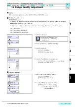
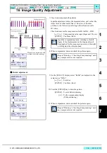
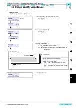
12. Select “BiDir” on the [SELECT] display.
[
] / [
] : Switches
[ENTER] : Confirms (Next)
13. Press the [ENTER] key to draw the pattern.
[ENTER] : To start Pattern drawing
[
] : To the compensation display
(Without drawing)
14. Check and compensate the patterns.
The reference lines are drawn in going, and then the adjustment
lines are drawn at the same Y-coordinate positions in returning.
The position where the lines above are overlapped on one
vertical line is specified as the correct dot position (H1A: M-
color fixed)
Confirm that the dots are on the same line.
* The adjusting procedure is the same although the drawing
pattern is different depending on mode.
[
] / [
] : Compensating value input (Measured value)
[ENTER] : Confirms
15. When compensated, draw and check the patterns again.
#PRINT ADJUST
SELECT:BiDir
SiDir
ReDir
Pattern drawing
#PRINT ADJUST
BiDir:PRINT
900Hi BiDir WF1
900DPI BiDir : 0
-200.0~200.0
Check if the displacement
is almost equal in the right,
the center and the left of the
drawn area.
If the displacement is significantly different in the
right and left, other reasons are considered.
Repeat “Drawing -> Checking (Compensating)” until
any compensation is not required.
INSTALLATION GUIDE > Outputting Plots > Image Quality Adjustment
Model
JV400-130/160LX
Issued 2011.02.15 Revised 2013.10.10 F/W ver.
2.50
Remark
1.2
Summary of Contents for JV400-130LX
Page 49: ......
Page 50: ...D500698 22 30042014 2013 MIMAKI ENGINEERING CO LTD KF FW 2 50...


