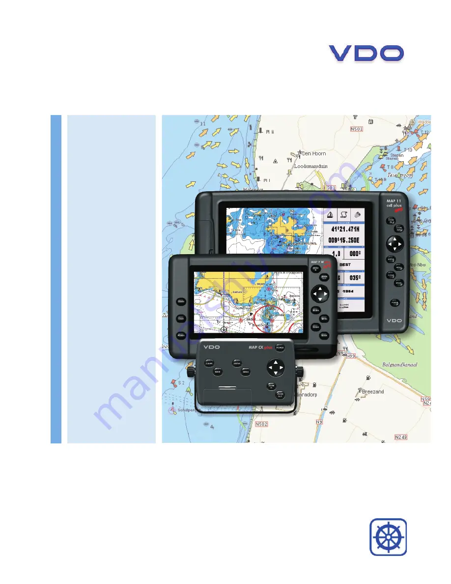
background image

VDO Chart Plotters

www.vdo-marine.com

_ MAP 7 V GPS

_ MAP 7 cs GPS

_ MAP 7 W/Wi/Plus GPS

_ MAP 11 csE/Plus GPS

VDO Marine

Office address: Kienzle Automotive GmbH 

Alexanderstr.37-39    45472 M

ü

lheim

Phone: +49 (0) 208/ 4950 5 177

Fax: +49 (0) 208/ 4950 5 353

E-mail: [email protected]

Part-Nr. NEW KI-0301-001-1207E 

 I 

Kienzle Automotive GmbH I Printed in Italy

© 2007 MAALLVDODX

We reserve the right to make changes in ava bility as well as 

technical changes without prior notice.

ila

Summary of Contents for MAP 11csE Plus GPS

Page 1: ...VDO Chart Plotters www vdo marine com _ MAP 7 V GPS _ MAP 7 cs GPS _ MAP 7 W Wi Plus GPS _ MAP 11 csE Plus GPS ...

Page 2: ... Internal GPS Receiver Fish Finder Video Input MAP 11csE Plus GPS 11 Sunlight Readable Color Display S5egVD11c External Smart GPS Receiver Video Input MAP cx Plus GPS Controller S5egVDctc External Smart GPS Receiver Video Input Copyright 2009 VDO Marine Germany All rights reserved Printed in Italy No part of this publication may be reproduced or distributed in any form or by any means or stored in...

Page 3: ...4 User Manual ...

Page 4: ... 1 SWITCHING ON OFF 19 Switching On 19 Switching Off 19 2 2 CHANGING BACKLIGHT AND CONTRAST 19 2 3 SELECTING THE USER INTERFACE LANGUAGE 19 2 4 SELECTING THE CHART LANGUAGEE 20 2 5 USING C MAP BY JEPPESEN DATA C CARD 20 2 6 SIMULATION MODE 20 2 7 CONTROLLING THE DISPLAY 21 Changing Display Mode 21 Chart with Engine Data 23 Engine Data page 23 Moving around the Chart and Changing Chart Scale 24 Fin...

Page 5: ...31 Displaying Track 31 Activating Deactivating Track Recording 31 Clearing Track 31 Selecting Track Number 31 3 5 INFO 32 Setting Automatic InfoE 32 Selecting Automatic Info 32 Displaying Expanded Info page Full Info 32 Info Tree and Expanded Info page 32 Info on objects with Pictures 32 Quick Info on Lakes 33 Full Info on Lakes 34 3 6 PORT TIDE INFO 34 Getting Port Info 34 Getting Tide Info 35 3 ...

Page 6: ...water Objects Settings 48 4 3 CONFIGURATIONS 48 4 4 ADVANCED SETTINGS 49 Setup menu 49 Navigate Menu 49 CompassE menu 50 External EngineE menu 50 4 5 AIS 51 AIS System Definitions 51 AIS Menu 52 To set the chart plotter for receiving AIS 53 Quick Info on AIS Target 53 4 6 SYSTEM INFORMATION 53 World Background Charts 53 Worldwide Background Update 53 Expert Functions 53 4 7 INPUT OUTPUT 54 Interna...

Page 7: ...4 PLACING CURSOR ON THE PTX ICON 69 6 4 1 Delete PTX 69 6 4 2 Goto PTX 69 6 4 3 MOBILARM PTX List Page 69 6 4 4 Show PTX 70 7 Fish Finder ONLY FOR MAP 7 CWI PLUS GPS 71 7 1 SETTING THE INTERNAL FISH FINDER ON 71 7 2 UNDERSTANDING THE FISH FINDER PAGE 71 7 2 1 Understanding the Echogram display 73 7 3 DISPLAYING THE FISH FINDER PAGE 74 7 3 1 How to select the Fish Finder page 74 7 3 2 Fish Finder F...

Page 8: ...TION AND REMOVING 91 EXTERNAL WIRING 92 TYPICAL CONNECTIONS 93 MAP 7cwi Plus GPS 95 FEATURES FUNCTIONS 95 TECHNICAL SPECIFICATIONS 96 FF MODULE 600W 50 200KHz 96 TECHNICAL SPECIFICATIONS 96 INSERTING REMOVING PROCEDURE 96 Inserting the C CARD 96 Removing the C CARD 97 CHART PLOTTER DIMENSIONS 97 INSTALLATION AND REMOVING 97 EXTERNAL WIRING 98 TYPICAL CONNECTIONS 98 MAP 11csE Plus GPS 101 FEATURES ...

Page 9: ...PS Connection 111 Autopilot Connection 111 External NMEA Connection 112 External Alarm Connection 112 C COM GSM PLUS Connection 112 Specification of CAN Interfaces MAP 11CSE PLUS GPS 113 List of the SAE J1939 71 measuring values October 1998 113 List of the SAE J1939 71 used October 1998 113 Easy Link Interface Specifications 113 Installing the Smart GPS External MAP 7W PLUS GPS MAP 11CSE PLUS GPS...

Page 10: ...al is related to all chart plotter models Whenever it is necessary a note has been inserted for those models with differences EXPERT FUNCTIONS It is possible to expand the functions set available on the chart plotter When the chart plotter comes from factory or after a RAM Clear see Chapter 8 only those menus items are visible which are of importance for the basic functions Due to this the chart p...

Page 11: ...MAP 7cwi Plus GPS Introduction to the basic information on the internal Fish Finder its features and use CHAPTER 8 Maintenance User maintenance guidelines CHAPTER 9 Terms List of the terms and abbreviations used in the User Manual MAP 7w Plus GPS MAP 7wi Plus GPS Introduction to the basic information on MAP 7w Plus GPS MAP 7wi Plus GPS chart plotter its features and use Installation of the chart p...

Page 12: ...ys Avoid overheating which may cause loss of contrast and in extreme cases a darkening of the screen Problems which occur from overheating are re versible when temperature decreases WARNING ON SERIAL PORTS CONNECTION Please be aware that the serial ports are not opto isolated and then the external device is electrically connected to the chart plotter This allow the connection of high speed devices...

Page 13: ...he engine compartment blower for a certain time before starting work in a gasoline engine compartment Check that there is enough room behind the installation opening Pre drill the opening and complete with keyhale saw respect the safety instructions of the hand of tool manufacturer Use insulated tools if you must work disabling the power supply The electrical outputs of the chart plotter and the c...

Page 14: ... x without making changes if you are not into a menu sets the Home mode the cursor x x x is centered on ship s position for 1 second activates the Video Input 2 x ENTER if you are in chart page opens a menu to place Marks x x x Waypoints Goto EBL VRM if you are in chart page opens a menu to place MOB x x x if you are into a menu confirms selection x x x for 1 second activates the Video Input 1 x x...

Page 15: ...idge diagrams and nav aids Multilanguage Support displays charts in the local character set True Type Font improves text on chart for optimal reading Presentation Features Clear View advanced legibility techniques providing more chart data on the screen Clear Info sophisticated Human Dictionary to translate Nav Aid ab breviations found on paper charts Dynamic Nav Aids an innovative and dynamic pre...

Page 16: ...each satellite back to earth By knowing the position of 3 or 4 satellites and calculating various time differences between transmitted signals the GPS receiver can determine its present position anywhere on earth and thanks to continuous updates calculate speed and course information How GPS works Currently the GPS constellation consists of 26 orbiting satellites including 3 spares but this number...

Page 17: ...ng Accuracy HDOP The GPS fix accuracy is due to the locations of 3 satellites in the sky High accuracy is obtainable when the satellites are widely scattered in the sky on the contrary accuracy is reduced when the satellites have gathered in a narrow space In the following figure in both cases it is possible to obtain the GPS fix but in the left case the accuracy will be higher than the right Fig ...

Page 18: ...GHT AND CONTRAST You can change the level of backlight and contrast for the screen LIGHT for 1 second backlight increases At the next pressing and holding down it will decreases CONTR First pressure of the key increases the value till you keep it pressed next pressure of the key decreases the value till you keep it pressed MAP 11csE Plus GPS POWER use cursor to adjust backlight levels and or contr...

Page 19: ...t to Off and Chart Language is set as the User Interface Language selection if available on the chart data otherwise is set to English b If the cartographic data is changed for example the C CARD is removed or replaced Chart Language settings should be verified and if necessary changed 2 5 USING C MAP BY JEPPESEN DATA C CARD The chart plotter has a built in world map To use the chart plotter as a ...

Page 20: ... 7 for Fish Finder information Cursor or Ship Coordinates Distance and Bearing from Ship to Cursor from Ship to Target if Target is set from Ship to MOB if MOB is set Chart Scale Speed Over Ground Course Over Ground Map Datum selected Charting or Navigation Home Ship icon if in Charting the displayed icon is Fix received Indication if fix is not received if a Differential GPS signal is received Fi...

Page 21: ...und Fix Status Altitude Date and time Tracked but not used Satellite Bars to indicate S N Ratio Horizontal dilution of precision Index for position fixing accuracy Vertical dilution of precision Index for position fixing accuracy Fig 2 6d Example of GPS page Fig 2 7e Example of Navigation Data Fig 2 7f Example of 3D Navigation Data if Target is set ...

Page 22: ...ideo signal source is shown MAP 11csE Plus GPS Other pages are available Chart with Engine Data and Engine Data pages shown in the following pictures Chart with Engine Data The engine data are shown on the right beside the chart Fig 2 7h Example of Chart with Twin Engine Data Engine Data page Engine Data will be displayed according to the setting of the chart plotter i e Fig 2 7i Example of Single...

Page 23: ...NU MENU CONFIGURATIONS ENTER SCREEN AMPLI FIER ENTER ON ENTER Selecting Map OrientationE To select the orientation of your chart according to MENU MAP ORIENTATION ENTER The Map OrientationE function selects the orientation of your chart according to North the map is shown with North upwards Head the map is shown with the ship s current heading upwards Course the map is shown with the currently sel...

Page 24: ...ce on the cross between EBL and VRM ENTER DELETE ENTER The line and the circle disappears from the screen Editing EBL VRM Place on the cross between EBL and VRM ENTER EDIT ENTER moving the cursor to modify the line direction and the circle radius ENTER 2 10 MAN OVERBOARD MOB If a person or object is lost overboard and you need to return to the location use the MOB Man OverBoard function To activat...

Page 25: ...26 User Manual ...

Page 26: ...cursor key to modify Symbol Name Color Lat Lon CLEAR The User Point appears on the selected position with the new symbol and color NOTE To select the User Point presentation MENU MENU CONFIGURATIONS ENTER USER POINTS ENTER There are three possible choices by selecting OFF the User Point is not shown on the screen otherwise by selecting ON it is shown on the Chart page shown with symbol and name by...

Page 27: ... use the cursor key to select the Route number ENTER The Route shown by straight segments is centered on the screen with the cur sor on the central Waypoint This will then allow you to quickly work out which Route you have selected When you want to create a new Route select an open Route position in the list using the above procedure Creating a Route To create a new Route Place the cursor ENTER WA...

Page 28: ... in reverse order with Waypoints renumbered accord ingly If the destination is placed on the Route that Route cannot be reversed Selecting Route Report page To give information on Waypoints belonging to the selected Route MENU MENU ROUTE ENTER REPORT ENTER In this page it is possible to modify the Speed and Fuel consumption values MENU MENU ROUTE ENTER REPORT ENTER SPEED FUEL ENTER use the cursor ...

Page 29: ...CY ENTER The list of the dangerous objects found on the charts crossed by the Route is shown in the Route check report follow the procedure MENU MENU ROUTE ENTER ROUTE CHECK REPORT ENTER 3 3 GOTO FUNCTION This functions allows you to place the destination point and immediately start navigating to it Navigation to Waypoint Place the cursor on the desired Waypoint ENTER GOTO ENTER A circle surrounds...

Page 30: ... Setting a short time distance interval between Track points is best suited to navigate within a close or complex environment a greater time distance interval is best suited to a long voyage To select the interval at which the Track points are placed if you have selected Distance MENU MENU TRACK ENTER DISTANCE ENTER choice the desired step ENTER if you have selected Time MENU MENU TRACK ENTER TIME...

Page 31: ...ge The page combines the Info Tree and the Expanded Info pages this gives the advantage of showing the details of the object selected on the Info Tree while the cursor is moving through the Info Tree s items The upper side of the page contains the Info Tree and the Lower side contains the expanded information While moving the cursor through the Info Tree all the relevant information of the selecte...

Page 32: ...on Lakes Upon viewing the chart of a lake you will click on to query the available information immediately displayed with many details For example see the following picture Fig 3 5b Example of Lakes info When the cursor is placed over the icon the icons of the available services are shown Fig 3 5c Quick Info available services If you press ENTER all available information about the cartographic poi...

Page 33: ...n the screen appears Fig 3 5e Example of picture associated to the Fishing object 3 6 PORT TIDE INFO Getting Port Info Fig 3 6 Port Info icon The object Port Marina contains the information about the services available on the selected Port Marina and the area around it To get info on Port Marinas move the cursor on the Port Info icon The available information is shown in the Automatic Info window ...

Page 34: ...o Fig 3 6b Tide Info icon By placing the cursor over the Tide Station icon the chart plotter pops up the relative automatic info window see picture below and allows displaying a graphical page with the tides prediction of the selected object Fig 3 6c Automatic Info window on Tide Use ENTER to display the Tide Graph page It shows the Tide height variations during the 24 hours at any given day ...

Page 35: ... FUNCTION The Find function allows searching for the nearest Port Port Services Tide Stations Wrecks Obstructions Points Of Interest and Lakes loaded on the C CARD When the Find function is executed a list of available objects to search is shown Also the Find function allows to center the screen over a selected User Point on the Cursor position or at desired Coordinates NOTE Activating the Find fu...

Page 36: ... locate the ports on the map Press ENTER CLEAR to locate the selected Port by Name on the map Finding Port By Distance To select the Port By Distance function following the procedure MENU FIND ENTER PORT BY DISTANCE ENTER Shows the list of all ports stored on the C CARD in closest distance order and allows to locate the ports on the map Press ENTER CLEAR to locate the selected Port by Distance on ...

Page 37: ...CLEAR 3 8 ALARMS The chart plotter provides alarms for various functions You can enter the desired alarm range for each function Arrival Alarm To set an acoustic alarm to sound when the vessel is approaching the destination MENU MENU ALARMS ENTER ARRIVAL ALARM ENTER XTE Alarm To set an acoustic alarm to sound when the vessel is deviating from a defined course MENU MENU ALARMS ENTER XTE ALARM ENTER...

Page 38: ...ALARM RANGE ENTER Grounding Alarm ReportE To display the report of the dangerous objects currently detected MENU MENU ALARMS ENTER GROUNDING ALARM REPORT ENTER When any of the searched objects is found in the scanned area a tick marker is printed on the relative box to identify which dangerous objects have been cur rently detected Once the alarm condition is no longer present the relative tick mar...

Page 39: ...en naming a file you may have trouble finding a name that uniquely identifies the file s contents Dates for example are often used in file names however they take up several characters leaving you with little flexibility The secret is to find a compromise a point where you can combine a date with a word creating a unique file name The maximum length of the file name is 8 characters The characters ...

Page 40: ...41 User Manual MAP 11csE Plus GPS MAP cX Plus GPS Changing User C CARD Allows to select the slot in which the User C CARD is inserted MENU MENU USER C CARD ENTER CHANGE ENTER ...

Page 41: ...42 User Manual ...

Page 42: ...ndow is automatically closed if ZOOM is not pressed for 2 seconds and the selected zoom factor will be used at the next zoom in out Fonts SymbolsE MENU FONTS SYMBOLS ENTER It is possible to set the size of all names and symbols drawn on the charts selecting between Normal size the regular characters size and Large size NORMAL size LARGE size Fig 4 1 Example of Normal size on the left side and Larg...

Page 43: ...MIXING LEVELS ENTER When the map coverage at the current zoom level does not fill the entire screen the chart plotter draws the rest of the map expanding the cartographic information read from at most two zoom levels above the current zoom level For this reason the map is drawn three times firstly it draws the two levels before the current level and then the current level The area covered by the c...

Page 44: ...ay otherwise O Zoom red when the chart is over zoomed in more than twice nor mal scale gray otherwise Chart Lock red when the chart is zoomed in more than twice normal scale gray otherwise Best Map Red when a more detailed chart is available under the cursor position Data Off Red when at least one of the following objects or layers is turned off by the user Depths soundings Wrecks obstructions Tra...

Page 45: ...gs Land Settings Chart Set tings and Underwater Objects Settings Display Mode MENU OTHER MAP CONFIGURATIONS ENTER DISPLAY MODE ENTER Selects from a pre defined table what cartographic objects are displayed and which display options are set Pre programmed settings are user selectable from Full Medium Low Radar Tides Custom The table below shows the selections for each mode Setting Full Medium Low R...

Page 46: ...e Tide icons are shown on the charts on the basis of the current date and time the screen displays and changes arrows as date time changes Seabed Type Sets On Off the displaying of the Seabed Type Ports Services Sets On Off the displaying of the Ports and Services areas along shore with facilities for mooring downloading and uploading of ships generally sheltered from waves and winds Port installa...

Page 47: ...th the displaying of the Rocks Obstructions Sets Off Icon Icon Depth the displaying of the Obstructions Diffusers Sets Off Icon Icon Depth the displaying of Diffusers Wrecks Sets Off Icon Icon Depth the displaying of Wrecks NOTE Choose the options OFF the object is not visible independently of the selected Underwater Object Depth Value ICON the object icon is visible without tags in the range sele...

Page 48: ...the incorrect key is pressed or the function required cannot be executed the chart plotter emits three beeps Back Light TimeoutE Setsthetimevalueamong1 3 5 10Min afterthistimewhennokeyispressed thescreen and keyboard backlight is turned Off Auto InfoE Allows displaying information on cartographic object when the cursor is placed on it The Automatic Info On Points shows information when the cursor ...

Page 49: ...in an Automatic or manual mode by inserting the step for calculation of Magnetic Variation CalibrationE The variation table is used to match magnetic value readout on the chart plotter comparable with the value given by the compass of the boat In other words since the compass of the boat must be compensated due to the iron masses we use the same values given by the chart plotter This means that fo...

Page 50: ...n IMO vessels use VHF frequencies to Transmit details of their own vessel Receive details from other vessels or navigation aids within VHF range Information being transmitted from vessels over 300 tons that due to recent worldwide legislation are required to fit Class A AIS transponders Connecting to the chart plotter an AIS receiver please contact your local dealer vessels with AIS transponder wi...

Page 51: ...ith a cross through Activation Range Range around your boat where targets become active AIS target become active within this range Activation Range should be greater than CPA Limit by definition NOTE A Target is removed from the screen if data is not received for 10 minutes The maximum number of tracked Targets is 100 Depending on the scale the presentation of the Targets change to remove clutter ...

Page 52: ... page World Background Charts The internal background charts can be updated to include the MAX A and B level charts which provide improved marine data rivers lakes terrestrial data major streets highways railways etc Nav Aids depth areas territorial water areas etc by reading them from a special data C CARDs contact your local dealer All units must have the WorldWide Background upload function tha...

Page 53: ...nd 3 0 Kts high speed for car application MAP 7cwi Plus GPS Fish Finder Transmission The Fish Finder embedded is connected directly to the Port 2 To switch the inter nal Fish Finder transmission On Off follow the procedure MENU MENU INPUT OUTPUT ENTER FISH FINDER ON STANDBY ENTER Autopilot ConnectionE Connect the Autopilot to the serial Port n MENU MENU INPUT OUTPUT ENTER PORT n OUTPUT ENTER Then ...

Page 54: ...TER Port n ENTER Where n 1 2 3 for MAP 11csE Plus GPS n 1 4 5 for MAP 7cwi Plus GPS n 1 2 4 5 for MAP 7wi Plus GPS n 1 2 3 4 5 for MAP 7w Plus GPS MAP CX Plus C LinkE Sets the Primary or Secondary Station see dedicated Chapter MENU MENU INPUT OUTPUT ENTER C LINK ENTER Secondary Station Primary station ENTER External NMEAE Sets the displaying or not of the following items max four items in the Logi...

Page 55: ...nality so a Video Input image can be shown on a image at full screen MENU MENU INPUT OUTPUT ENTER VIDEO INPUT ENTER Select Video InputE Available options are the following Full Video Shows the image from the video camera at fullscreen PiP PictureInPicture Video Showsthecartographicimageatfullscreen with the image from the video camera on a window which can be moved up down and or right left using ...

Page 56: ...owingmessages are shown on a dedicated window Connnected Video Input Signal is XXXX The Video Mode will be activated XXXX can be PAL or NTSC the software automatically detects the type of Video Input source connected Once the Video Mode is active use the following keys to adjust video settings press POWER and move the cursor to adjust the contrast and backlight press ZOOM IN ZOMM OUT to adjust hue...

Page 57: ...TER to activate the Weather Download the whole data package see the previous Weather data package table are downloaded CLEAR allows to interrupt the data download At the end of the operation press CLEAR to close the window Copy from CARDE MENU MENU C WEATHER SERVICE ENTER COPY FROM CARD ENTER Allows the whole data package Weather loading from C CARD ForecastE MENU MENU C WEATHER SERVICE ENTER FORE...

Page 58: ...e Fish Finder is connected and powered On MODE more times to select the desired page Once the Fish Finder page is selected access the Fish Finder menu by pressing MENU For more information see the specific User Manual NOTE ONLY FOR Map 7cwi Plus GPS The Fish Finder is embedded into the chart plotter See also Cap 7 4 10 RADARE The Radar consists of a scanner unit which illuminates targets with micr...

Page 59: ...60 User Manual ...

Page 60: ...le the MIRROR C CARDs If a regular C CARD which has previously activated a MIRROR C CARD is removed even the MIRRORs C CARD will be not read anymore on the other unit C LinkE serial connection The two chart plotters should be connected via serial ports Any of the available ports can be used the software will recognize automatically the serial ports used A typical connection is as follows Chart Plo...

Page 61: ...nation to next Waypoint Bearing from Destination to next Waypoint Route Length Distance from Destination to Last Route Waypoint Remaining Route Legs Planned Cruising Speed Average Fuel Consumption Initial Fuel Load C LinkE Navigation Data can refer to Single Destination navigation Route Following navigation Values identified by are sent only for Route Following navigation The Destination Icon Navi...

Page 62: ... perpendicular criteria the Destination will not be moved to the next Waypoint on the Route MOB handling If the Navigation to the external Destination is active and ENTER MOB ENTER on MAP 7v GPS MOB is pressed on the Slave chart plotter the MOB is placed but the navigation to the MOB is not activated Notes While navigating to the external Destination the operating mode is switched to Master mode t...

Page 63: ...in Route No of Wpts in the Route from PCMPN 1 Remaining Waypoints No of Wpts from Dest to Last Wpt from PCMPN 1 Fuel Consumption Rate Planned Fuel Consumption Rate from PCMPN 1 Total Fuel Consumption Calculated Fuel consumption to navigate the whole Route Initial Fuel Load Volume of Fuel available before the navi gation was started Liters Remaining Fuel Volume of Fuel available Liters Distance to ...

Page 64: ...culated using Cruising Speed ETA to Destination Estimate Time of Arrival to the Destina tion Point calculated Current Time TTG To Destination ETA to Next Waypoint Estimate Time of Arrival to the Waypoint after the Destination calculated Current Time TTG To Next Waypoint ETA to Last Wpt Estimate Time of Arrival to the End of the Route calculated Current Time TTG To Last Wpt Quick Info Route Navigat...

Page 65: ...66 User Manual ...

Page 66: ... to MOBILARM as shown below for communications MENU MENU INPUT OUTPUT ENTER select any input port you want ENTER MOBILARM ENTER The chart plotter continuously verifies the communication status with MOBILARM instruments If there is no communication for more than one minute an alarm window appears 6 2 MOBILARM STATUS If you want to know information about the MOBILARM connected follow the procedure M...

Page 67: ...down 6 3 1 PTX is received When a PTX has beeen received the PTX data are saved on the chart plotter memory and the PTX icon appears on the map Fig 6 3 1 PTX icon All menus and or pages are closed and the chart is centered on the PTX received position The Audible Alarm starts beeping and a pop up warning window appears to notify that a PTX has been received MOBILARM 33 27 090N 220 34 020W Id Time ...

Page 68: ...verboard or Recovered appears MOBILARM PTX OVERBOARD 41 13 334N 009 30 702E Id Time 000001A0 10 16 79 PM Fig 6 4 Example of PTX information window 6 4 1 Delete PTX The Delete PTX function permamently removes the selected PTX from the chart plotter memory and from the chart display Move the cursor over the PTX to delete Press ENTER using the cursor select DELETE and press ENTER A warning pop up win...

Page 69: ...has been activated close all menus data pages if open and center the chart selected PTX DELETE Deletes the selected PTX SHOW Centers the chart on the selected PTX SHOW ALL Selects the best chart scale to see al PTX icons on the map at the same time 6 4 4 Show PTX The Show function is available when PTX has beeen received again it is already present on the chart plotter memory and it is the active ...

Page 70: ... by the receiver processed and sent to the display The speed of sound in water is roughly 4800 ft sec so the time lapse between the transmitted signal and the received echo can be measured and the distance to the object determined Fig 7 Fish Finder working principle 7 1 SETTING THE INTERNAL FISH FINDER ON The Fish Finder driver is embedded on the chart plotter it is connected directly to the dedic...

Page 71: ...nder the boat See the following Par 7 2 2 for more information Color Bar Colored scale located on the left side of the screen that shows the colors used in the Echogram to represent the echoes strength The color on the top of the bar represents the maximum sonar strength while the color on the bottom of the bar represents the minimum sonar strength Digital Depth Readout of the current bottom depth...

Page 72: ...he Echogram display The main elements that can be easily distinguished into an Echogram are Fig 7 2 1 The Fish Finder Echogram Fishes Fishes are represented as arcs because of the cone angle of the transducer In fact as the boat passes over the fish the leading edge of the cone strikes the fish causing a display pixel to be turned on As the boat passes over the fish the distance to the fish decrea...

Page 73: ...profile recorded by the Fish Finder When the echo sounder is set in auto range mode it is automatically kept in the lower half of the screen Other Elements Large anchoring cables are returned by the echo sounder as very long and narrow arcs on the screen 7 3 DISPLAYING THE FISH FINDER PAGE This section will take you through the frequently used operations and assist you to customize the look of the...

Page 74: ...m 2X and no zoom 7 3 3 Dual Frequency page To display the Fish Finder Dual Echogram follow this procedure MODE more times until the Fish Finder Dual Frequency page is displayed Fig 7 3 3 Fish Finder Dual Frequency mode The Cursor key Moving the cursor to the right or the left moves the Variable Depth Marker VDM between the 50 and 200kHz displays Moving the cursor up or down will move the VDM up an...

Page 75: ... window When in Chart Fish mode pressing MENU if the focus the active window in on the Chart the Functions menu is shown Pressing again MENU opens the Fish Finder Setup menu and moves the focus to the Fish Finder if the focus the active window in on the Fish Finder the Fish Finder Setup menu is shown Pressing again MENU opens the Functions menu and moves the focus to the Chart NOTE When focus is o...

Page 76: ... Finder Echogram is automatically moved up down as to keep the Bottom Line always visible in the lower half of the screen NOTE Moving the Cursor key up down displays the Variable Depth Marker VDM switching the Fish Finder in Marker Zoom mode 7 4 2 The Marker Zoom The Marker Zoom mode is activated either when the Fish Finder is in Manual Range mode see Par 7 5 3 or the Depth Cursor is displayed on ...

Page 77: ... A Scope On Surface Noise Filter Off Cruise Gain Mode Auto Range Mode Auto Frequency do not change Shift 0 STC Short if Freq 200kHz and Mid if Freq 50kHz Scrolling Speed 10 Fish Symbols Echo A Scope On Surface Noise Filter 4 7 5 2 Gain Mode Selects Auto or Manual MENU GAIN MODE ENTER 7 5 3 Range Mode Selects among Manual Auto Range and Bottom Lock When in Manual Range Mode it is possible to set Sh...

Page 78: ...Time Constant STC Strenth If STC is Custom it is possible to change the Strength of the Sensitivity Time Constant Surf Noise Filter2 This function implements an advanced time varying filter that allows suppressing the surface clutter efficiently while leaving fish targets visible NOTE1 The Frequency value is only displayed to select the desired frequency see the previous Par 7 5 7 NOTE2 Thus impos...

Page 79: ...er than the value set Deep Water Alarm Triggers an alarm when depth becomes deeper than the value set Temp Upper Triggers an alarm when the transducer reports a temperature from TEMP 1 sensor above the value set Temp Lower Triggers an alarm when the transducer reports a temperature from TEMP 1 sensor below the value set Temp Rate Triggers an alarm when the transducer reports a temperature from TEM...

Page 80: ...ll Marks Routes stored Track plots and destinations It will also return all selections Input Data Format Autopilot selection etc to original default values Before this step you have the option of saving user Marks Track history and Routes to a User C CARD this is an optional purchase from your dealer To confirm to clear RAM press ENTER again but if this time you do not wish to clear RAM press CLEA...

Page 81: ...face format If the screen is blank the connection may be interrupted and no data is being received Use ZOOM IN to stop or con tinue after pause data displaying ENTER to show data in hex or ASCII mode normal or small and CLEAR to exit Modem test Checks the Modem connections Press ENTER to select the desired Port related to the connections made to the Port to which the Modem C COM is connected Exter...

Page 82: ...cal mark as a fixed aid to navigation Boost Pressure Boost pressure in boosted engine Buoy Floating object moored to the sea bottom in a particular charted place as an aid to navigation Buoys and Beacons Used to indicate to mariners recommended or established routes underwater dangers restrictions and regulations BRG Bearing Angle between the North True or Magnetic and a destination The horizontal...

Page 83: ...eas Sea areas included in the user selectable range of minimum and maximum depth limits The sea area that is beyond the selected range is filled by an uniform white color the sea area that is inside the selected range is filled by ordinary multicolor shading The Spot Soundings and Depth Contours are dis played on the range only Depth Line Also called Bathymetric Line Imaginary line connecting poin...

Page 84: ...al Dilution Of Precision Parameter indicating the precision of the positioning system GPS The smaller HDOP value indicates higher position accurately Home mode All operations refer to the ship s position Intake Manifold Temperature Intake air temperature Landmarks Landmarks are any prominent object such as monument building silo tower mast on land which can be used in determining a location or a d...

Page 85: ...America It is an international standard that enables equipment from many different manufactures to be connected to gether and share information OSGB Ordinance Survey of Great Britain Coordinate system describing only Great Britain charts Generally used with GBR36 datum which also describes only Great Britain charts This coordinate system cannot be used in any other part of the world Pair Two selec...

Page 86: ... Water Speed of the vessel relative to the water Spot Soundings Depth of the water in a specific and charted position It is represented on the map by its own value expressed in the current depth unit STR Steering Difference between COG and CTS If COG is 25 and CTS is 30 then STR is 5 Right Total Engine Hours Total operating hours of the machine This value is not calculated in the plot ter but read...

Page 87: ...e and the bearing to the destination VRM Variable Range Marker VRM is a circle and its radius is determined by the user The circle s center is the ship s or cursor position WAAS Wide Area Augmentation System The Federal Aviation Administration FAA in cooperation with other DOT or ganizations and DOD is augmenting the GPS SPS with a satellite based aug mentation system the WAAS It will provide a si...

Page 88: ...function for ports tidal information serrvice facilities Positional information from GPS GPS Signal Status page Navigation Data pages 1000 Waypoints Marks and 20 Routes 51 Waypoints max per Route Create Move Insert Edit or Erase Waypoint Create Move Edit or Erase Mark Automatic Info on User Points Navigation to Destination Create Save Name Edit or Follow a Route Route Data Report and User Points M...

Page 89: ...ter was purchased from Quick disconnect bracket and its protective cover Chart plotter s protective cover Fuse 2 Amp fuseholder MAP 7w Plus GPS Flush mounting kit MAP 7w Plus GPS Smart DGPS WAAS Receiver with cable 15 mt 45 feet User Manual INSERTING REMOVING PROCEDURE Inserting the C CARD Open the door hold the C CARD by the long side so that you can see the label and gently push the C CARD into ...

Page 90: ...1 7 88 5mm 3 5 112 5mm 4 4 203 5mm 8 92mm 3 6 151mm 5 9 241mm 9 5 153mm 6 177 8mm 7 INSTALLATION AND REMOVING 115mm 4 5 45mm 1 8 100mm 3 9 126mm 5 220mm 8 7 211mm 8 3 GRAY parts are present ONLY on chart plotter WITH GPS INTERNAL MAP 7w Plus GPS flush installation and MAP 7w Plus GPS MAP 7wi Plus GPS bracket installation ...

Page 91: ...92 User Manual EXTERNAL WIRING External Wiring for MAP 7w Plus GPS External Wiring for MAP 7wi Plus GPS ...

Page 92: ...OWER GND POWER 10 35Vdc INPUT1 SIGNAL RETURN OUTPUT1 INPUT2 OUTPUT2 INPUT3 OUTPUT3 SIGNAL RETURN FUNCTION Autopilot Connection on Port 2 NMEA0183 DEVICE NMEA0183 OUTPUT NMEA0183 INPUT SIGNAL RETURN FUNCTION QUICK DISCONNECT BRACKET CABLE DESCRIPTION WIRE COLOR BLACK RED WHITE GREEN YELLOW BROWN GRAY ORANGE PINK BLUE POWER SUPPLY GND POWER SUPPLY NMEA0183 C COM SIGNAL RETURN NMEA0183 180 180CDX C C...

Page 93: ...POWER 10 35Vdc INPUT 1 SIGNAL RETURN OUTPUT 1 BLACK RED WHITE GREEN YELLOW POWER SUPPLY GND POWER SUPPLY C COM SIGNAL RETURN C COM FUNCTION C COM GSM Plus CABLE WIRE COLOR FUNCTION GND POWER SUPPLY C COM TX C COM TX C COM RX BLACK RED WHITE GREEN YELLOW C COM Connection on Port 1 ...

Page 94: ...ports tidal information serrvice facilities Positional information from GPS GPS Signal Status page Navigation Data pages 1000 Waypoints Marks and 20 Routes 51 Waypoints max per Route Create Move Insert Edit or Erase Waypoint Create Move Edit or Erase Mark Automatic Info on User Points Navigation to Destination Create Save Name Edit or Follow a Route Route Data Report and User Points Marks Waypoint...

Page 95: ...nal Processing Speed Temperature Sensor if available on transducer Alarms shallow water depth Fish temp Trip Log Fish Symbols STC Interference Rejection Automatic noise reduction A scope White Line Zoom x2 x4 Auto range gain frequency shift ping rate When the package containing the chart plotter is first opened please check it for the following contents if any parts are missing contact the dealer ...

Page 96: ... remove the C CARD inserted in the chart plotter open the door 1 The C CARD will eject out of the chart plotter slot remaining fixed into the door 2 Then remove the C CARD from the slot 3 CHART PLOTTER DIMENSIONS INSTALLATION AND REMOVING ...

Page 97: ...98 User Manual EXTERNAL WIRING TYPICAL CONNECTIONS Autopilot Connection on Port 1 External NMEA Connection on Port 1 ...

Page 98: ...POWER 10 35Vdc INPUT 1 SIGNAL RETURN OUTPUT 1 BLACK RED WHITE GREEN YELLOW POWER SUPPLY GND POWER SUPPLY C COM SIGNAL RETURN C COM FUNCTION C COM GSM Plus CABLE WIRE COLOR FUNCTION GND POWER SUPPLY C COM TX C COM TX C COM RX BLACK RED WHITE GREEN YELLOW C COM Connection on Port 1 ...

Page 99: ...100 User Manual ...

Page 100: ...Search function for ports tidal information serrvice facilities Positional information from GPS GPS Signal Status page Navigation Data pages 1000 Waypoints Marks and 20 Routes 51 Waypoints max per Route Create Move Insert Edit or Erase Waypoint Create Move Edit or Erase Mark Automatic Info on User Points Navigation to Destination Create Save Name Edit or Follow a Route Route Data Report and User P...

Page 101: ...o signals automatically selected Video Output VGA compatible optional adapter cable Cartography C MAP BY JEPPESEN C CARD Operating temperature range 0 55 C 32 131 F Memory Non volatile Keyboard Silicon rubber backlight Weight 1 6 Kg When the package containing the chart plotter is first opened please check it for the following contents if any parts are missing contact the dealer the chart plot ter...

Page 102: ...he C CARD out of one of the two slots as shown in the right side of the previous picture CHART PLOTTER DIMENSIONS 329mm 13 211mm 8 3 160 2mm 6 3 221mm 8 7 125mm 4 9 230 5mm 9 1 264m m 10 4 INSTALLATION AND REMOVING VOUT 40m m 1 6 140 5 5 225mm 8 56 175mm 6 9 VOUT ...

Page 103: ...OR CABLE AUX IN I O CABLE CONNECTION ENGINE POWER I O CONNECTOR CABLE VIDEO OUTPUT CONNECTOR 1 2 3 CAM CONNECTORS PIN OUT ON UNIT GND COMMON PWR 10 35Vdc SIGNAL VIDEO INPUT CONNECTOR PIN 1 2 3 FUNCTION TYPICAL CONNECTIONS GPS Connection SMART GPS SENSOR POWER I O POWER SUPPLY 1 POWER I O CABLE POWER I O CABLE PWR GND COMMON POWER INPUT 10 35 Vdc INPUT 1 COMMON OUTPUT 1 BLACK RED WHITE GREEN YELLOW...

Page 104: ...K RED WHITE GREEN YELLOW PIN 1 2 3 4 6 WIRE COLOR FUNCTION AUTOPILOT COMMON RX Autopilot on Port 1 POWER I O POWER SUPPLY 1 POWER I O CABLE POWER I O CABLE PWR GND COMMON POWER INPUT 10 35 Vdc OUTPUT 2 INPUT 2 BLACK RED GRAY BROWN PIN 1 2 5 7 WIRE COLOR FUNCTION AUTOPILOT COMMON RX Autopilot on Port 2 External NMEA Connection EXTERNAL NMEA DEVICE POWER I O POWER SUPPLY 1 POWER I O CABLE POWER I O ...

Page 105: ...ER I O POWER I O CONNECTOR POWER I O CONNECTOR 1 2 3 4 5 6 7 8 PIN CABLE COLOR FUNCTION BLACK RED WHITE GREEN GRAY YELLOW BROWN BLUE PWR GND COMMON PWR 10 35 Vdc Used by C COM Used by C COM OUTPUT2 Used by C COM INPUT2 OUTPUT EXTERNAL ALARM External Alarm Connection POWER I O 1 2 8 PIN CABLE COLOR FUNCTION PWR GND COMMON PWR 10 35 Vdc OUTPUT EXTERNAL ALARM Open Collector POWER I O CABLE POWER I O ...

Page 106: ...ormation serrvice facilities Positional information from GPS GPS Signal Status page Navigation Data pages 1000 Waypoints Marks and 20 Routes 51 Waypoints max per Route Create Move Insert Edit or Erase Waypoint Create Move Edit or Erase Mark Navigation to Destination Create Save Name Edit or Follow a Route Automatic Info on User Points Route Data Report and User Points Marks Waypoints List pages Fi...

Page 107: ... bracket Power supply and I O CBC0FS0804 I O cable CBC0FS0603 AUX IN I O cable 1 5 mt 5 9 feet Video Output cable Fuse 1A 2 pcs cable fuse holder 2 pcs User Manual INSERTING REMOVING PROCEDURE Inserting the C CARD Hold the C CARD by the short inclined side so that you can see the C MAP BY JEPPESEN label Open the C CARD slot s door pressing 1 to the bottom 2 Gently push the C CARD into one of the t...

Page 108: ...LATION AND REMOVING WARNING In order to protect the chart plotter video board please make sure that the power cables of the monitor and of the chart plotter are physically separated with protection against electrical discharge Flush installation ...

Page 109: ... RED GREEN BROWN NC NC BLACK YELLOW SHIELD WIRE COLOR FUNCTION 1 GND 2 VCC 3 R 4 G 5 B 6 HSYNC 7 VSYNC 8 N C 9 BRIGHTNESS CONTROL PIN FUNCTION GND COMMON POWER OUTPUT 10 35 Vdc INPUT 4 GND OUTPUT 5 OUTPUT 4 INPUT 5 EXTERNAL ALARM OUTPUT BLACK RED WHITE GREEN GRAY YELLOW BROWN BLUE PIN 1 2 3 4 5 6 7 8 WIRE COLOR FUNCTION FUSE POWER SUPPLY 1A FUSE 1A NOTE Add in series to power cord both Red and bla...

Page 110: ... POWER INPUT 10 35 Vdc OUTPUT 2 INPUT 2 BLACK RED GRAY BROWN PIN 1 2 5 7 WIRE COLOR FUNCTION GPS SENSOR CABLE GPS SENSOR CABLE POWER OUTPUT 10 35 Vdc GPS RX GPS TX GND COMMON RED GREEN BROWN BLACK YELLOW SHIELD WIRE COLOR FUNCTION GPS on Port 2 SMART GPS SENSOR GPS SENSOR CABLE GPS SENSOR CABLE POWER OUTPUT 10 35 Vdc GPS RX GPS TX GND COMMON RED GREEN BROWN BLACK YELLOW SHIELD PIN 1 2 3 6 GPS ANTE...

Page 111: ... CABLE POWER I O CABLE PWR GND COMMON POWER INPUT 10 35 Vdc OUTPUT 2 INPUT 2 BLACK RED GRAY BROWN PIN 1 2 5 7 WIRE COLOR FUNCTION EXTERNAL NMEA DEVICE COMMON TX RX External NMEA on Port 2 External Alarm Connection POWER I O 1 2 8 PIN CABLE COLOR FUNCTION PWR GND COMMON PWR 10 35 Vdc OUTPUT EXTERNAL ALARM Open Collector POWER I O CABLE POWER I O CABLE BLACK RED BLUE 1 2 8 1 Current MAX 300mA POWER ...

Page 112: ... 5 4 65270 Exhaust gas temperature 5 2 5 8 65270 Transmission Oil Pressure 5 2 5 24 65272 Transmission Oil Temperature 5 2 5 17 65272 Fuel Level 5 2 5 71 65276 Turbocharger 1 Turbine Inlet Temperature 5 2 5 207 65176 Turbocharger 2 Turbine Inlet Temperature 5 2 5 207 65176 Electrical Potential Voltage 5 2 5 75 65271 Battery Potential Voltage Switched 5 2 5 77 65271 Battery 2 Potential Voltage 5 2 ...

Page 113: ...114 User Manual ...

Page 114: ...standard thread used on a wide range of mounting brackets including the swivel joints commonly used for angled surfaces However due to the manufacturing process of these mounting brackets you may see that there is some slop when tightening down the antenna to the bracket This is of no concern however as the antenna must be tightened until the antenna stops rotat ing on the antenna mounting bracket...

Page 115: ...e cable go through the central hole 4 Apply a small coat of RTV to the underside of the antenna 5 Place the antenna and then screw it with the three M3 screws Installing GPS Antenna III Dimensions 60mm 2 63 41mm 1 61 98mm 3 86 GPS Antenna Dimensions ...

Page 116: ...55 61 62 63 C Link serial connection 61 C Weather Service 57 Cable Wiring 56 Calibrate Aux Temp 80 Calibrate Sound Speed 80 Calibrate Water Speed 80 Calibrate Water Temp 80 Calibration 50 CAN 83 CAN Interfaces 113 Cartographic Data 16 CARTOGRAPHY 15 CAUTION 13 Chain 83 Changing Chart Scale 24 Changing Display Mode 21 Changing User C CARD 41 Chart Boundaries 47 Chart Language 20 48 Chart Lock 48 CH...

Page 117: ...50 Engine Speed 84 Engine Units 50 Enhanced Mixing Levels 16 Enhanced Port Info 16 Enhanced Turbo Zoom 16 ENTER 15 Estimated Time of Arrival 84 ETA 84 Exhaust Gas Temperature 84 Expanded Info 32 Expert Functions 12 53 External Alarm 39 55 82 External Alarm Connection 106 112 External Engine menu 50 External NMEA 55 External NMEA Connection 54 93 98 105 112 External Output 55 External Power 55 Exte...

Page 118: ...LOG Calibration 49 LOG Speed 85 Logic Data Display Page 55 Longitude 85 Loran 85 M Magnetic Deviation 86 Magnetic Variation 86 Maintenance 81 Man OverBoard 25 Map Datum 50 Map menu 43 Map Orientation 24 44 Map Orientation Res 50 Marine Settings 46 Mark 27 86 Marker Zoom 77 Master Chart Plotter 62 MASTER mode 61 MAX 15 MENU 15 Mixing Levels 16 44 MMSI 52 MOB 25 MOBILARM 67 68 69 70 MOBILARM status ...

Page 119: ...ecting Active Route 28 Selecting Route Color 28 Selecting Track Color 31 Selecting Track Number 31 Send Routes Marks 55 Sending Route 29 Sending User Point 28 Sensitivity Menu 79 Sensitivity sub menu 75 serial port 13 Serial Ports 82 Set Defaults Settings 80 Setup menu 49 Shallow Alarm 80 Shallow Water 29 Shift 78 Shoreline Constructions 29 Show PTX 70 Simulation Mode 20 Simulator 20 Slave Chart P...

Page 120: ...oint presentation 27 User Points List 27 UTC 88 UTM 88 V Value Added Data 48 Variable Depth Marker VDM 73 Variable Range Marker 25 88 Variation 50 88 Video Input 23 56 VMG 88 voltage 19 VRM 25 88 VTG 55 W WAAS 88 WARNING 13 Warning Message FF 72 Water Temperature 72 79 Waypoint 27 28 29 88 WCV 55 WGS 84 88 White Line 74 79 Wind Speed 48 World Background 53 Wrecks 29 37 48 X XTE 38 55 88 XTE Alarm ...

Reviews: