© 2014 MIMAKI ENGINEERING CO.,LTD.
4.2
P.7
4.2 Assembling the Stands and the Device
R.1.1
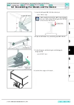
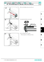
15. Fix the legs on the main body with the screws (CS5x15SMW
8pcs).
Use the attached hexagon wrench.
16. Attach the Stand reinforcement plate.(Right and left)
screw: P4x10SMW x 8
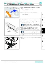
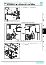
17. Remove two screws each from the right and leftsides and detach
the Stay1.
If the screw holes of the main unit and of the stand do not fit,
follow the steps below.
(1), Loosen the screws (CS5x15SMW, 4pcs) of the upper stand
stay on the back of the main unit, turning one-half with the
supplied hexagonal wrench.
(2), Fitting the screw holes of the main unit and the stand,
temporarily tighten the screws (CS5x15SMW, 8pcs).
(3), Fully tighten the screws that were loosened on the step (1).
(4), Fully tighten the screws that were temporarily tightened on the
step (2).
Be sure to turn "one-half" to loosen the screw.
Do not loosen the screw of the lower stand stay on
the front of the main unit.
Hold down the stand stay and tighten the screw.
Stand stay
Stay 1
INSTALLATION GUIDE > Printer Assembly > Assembling the Stands and the Device
Model
JV400-130/160LX
Issued
2011.02.15 Revised 2013.04.15 F/W ver.
Remark
1.1
Summary of Contents for JV400-130LX
Page 49: ......
Page 50: ...D500698 22 30042014 2013 MIMAKI ENGINEERING CO LTD KF FW 2 50...


