


Not for
Reproduction
20
Installation
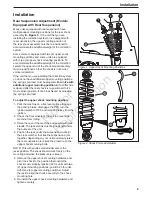
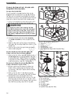
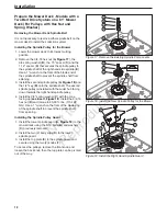
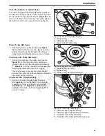
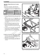
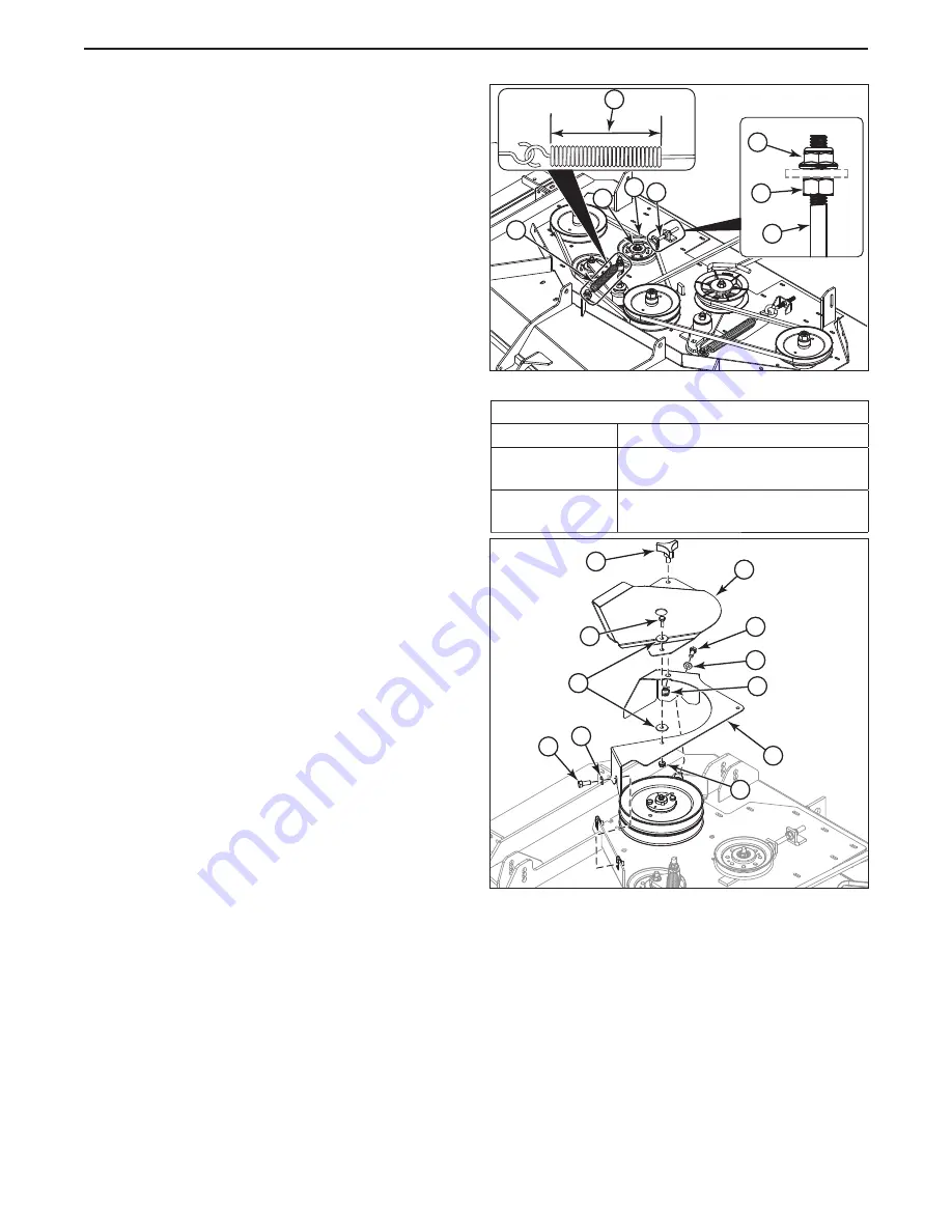
Installing the Mower Deck Spindle Belt
1. Refer to
Figure 20
for proper spindle belt
alignment. Make sure that the V-side of the belt (
A,
Figure 20
) is in the grooves of the center spindle
pulley (
G
) and the front idler pulley (
H
).
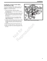
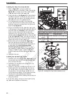
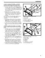
2. Loosen the jam nut (
A,
Figure 23
) on the carriage
bolt (
B
) and the 3/8” nut (
C
) that secures the rear
idler pulley (
D
) to the deck. This will allow the rear
idler pulley to move in it’s adjustment slot.
3. Turn the adjustment nut (
E
) so that the pulley
moves closer to the front of the mower deck. This
will make it easier to re-install the short right hand
deck belt (
A,
Figure 20
).
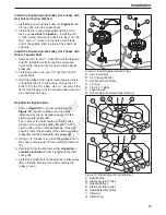
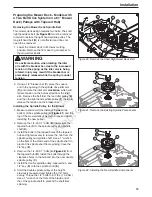
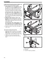
4. Using a 1/2” breaker bar (
C
) place the square end
in the opening in the spindle drive idler arm (
D
) and
rotate the idler arm
clockwise
, which will relieve
tension on the belt exerted from the idler arm.
Install the belt on the lower groove of the double
spindle pulley (
A,
Figure 22
) and then the rear idler
pulley (
D,
Figure 23
). Make sure that the V-side of
the belt runs in grooves of all four pulleys. Carefully
release the tension on the breaker bar.
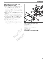
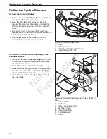
5. Measure the coil-to-coil length (
F,
Figure 23
) of
the short right hand belt tensioning spring (
G
).
The measurement should equal the measurement
as indicated in the
Short Right Hand Belt
Tensioning Spring Length
chart. If not, turn
the adjustment nut (
E
) until the measurement is
achieved. Tighten the jam nut (
A
) and the 3/8”
nut (
C
) that secures the rear idler pulley (
D
) to the
deck.
6. Install the floor pan.
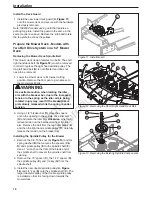
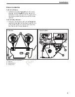
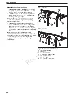
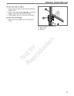
Installing the Spindle Pulley Guard
1. Install the lower spindle guard (
A,
Figure 24
) to the
mower deck using the 5/16 bolts (
B
) and washers
(
C
) previously removed.
2. Install the body clip (
D
) into the back hole of the
lower spindle guard.
3. Install a 1/4-20 X 3/4” bolt (
E
) down through a 1/4”
fender washer (
F
), the top plate (
G
), the second
1/4” fender washer, the lower spindle guard, and
secure with a 1/4” nylock flange nut (
H
). Do not
over-tighten the hardware. The top plate should be
able to pivot on the hardware just installed.
4. Install the top plate to the spindle guard and secure
using the knob (
I
).
To access the pulleys, remove the knob and then the
top plate can be pivoted out of the way.
G
B
D
C
F
B
A
E
I
E
G
B
C
D
H
A
C
B
F
Figure 23. Installing the Short Right Hand Deck Belt
Figure 24. Installing the Right Hand Spindle Guard
Short Right Hand Belt Tensioning Spring Length
Serial Number
Measurement
2017702695 &
below
6-1/8” (15,6 cm) ± 1/8” (0,32 cm)
2017702696 &
above
6-3/4 (17,1 cm) ± 1/8” (0,32 cm)