


Not for
Reproduction
19
Installation
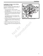
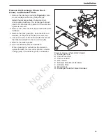
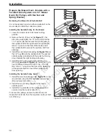
Preparing the Mower Deck - Models with
a Two Belt Drive System on a 61” Mower
Deck (Pulleys with Tapered Hub)
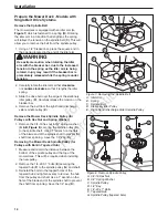
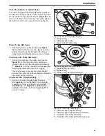
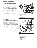
Removing the Mower Deck Spindle Belt
This mower deck design features two belts. The short
right hand deck belt (
A,
Figure 20
) must be removed
in order to replace the right hand spindle pulley. The
long left hand belt (
B
) is not affected and does not
need to be removed.
1. Lower the mower deck to it’s lowest cutting
position. Remove the floor pan to gain access to
the mower deck belts.
2. Using a 1/2” breaker bar (
C
) place the square
end in the opening in the spindle drive idler arm
(
D
) and rotate the idler arm
clockwise
, which will
relieve tension on the belt exerted from the idler
arm. Remove the belt from the rear idler pulley (
E
)
and then the right hand spindle pulley (
F
). Carefully
release the tension on the breaker bar.
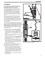
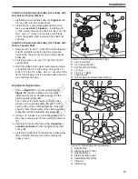
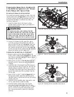
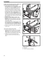
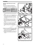
Installing the Spindle Pulley for the Blower
1. Measure and record the distance between the
bottom of the spindle pulley (
A,
Figure 21
) and the
top of the mower deck. This will be required when
installing the new pulley.
2. Remove the 1/4-20 X 1” bolts (
B
) that secure the
tapered hub (
C
) to the spindle pulley and spindle
shaft (
D
).
3. Install the bolts in the tapped holes of the tapered
hub and tighten evenly to remove the hub from the
spindle pulley and spindle shaft. Use a 1” wrench
on the flats of the blade end of the spindle shaft to
prevent the spindle shaft from spinning. Save the
1/4” key (
E
).
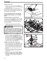
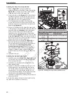
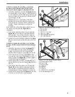
4. Remove the 1/4-20 X 1” bolts (
A,
Figure 22
) from
the tapered hub (
B
). Install the bolts through the
clearance holes in the hub and into the new double
spindle pulley (
C
).
5. Install the double spindle pulley, tapered hub, and
1/4” key (
D
) onto the spindle shaft (
E
).
6. Hold the double spindle pulley at the height
previously measured and tighten the 1/4” bolts
evenly. Torque the 1/4” bolts to 8 ft. lbs. (10,9 Nm).
Use a 1” wrench on the flats of the blade end of
the of the spindle shaft to prevent the shaft from
spinning.
C
F
E
A
B
H
G
D
B
C
A
E
D
A
B
C
D
E
Figure 20. Remove the Short Right Hand Deck Belt
Figure 21. Remove the Existing Spindle Components
Figure 22. Installing the New Spindle Components
WARNING
Use extreme caution when rotating the idler
arm with the breaker bar, due to the increased
tension in the spring as the idler arm is being
rotated. Injury may result if the breaker bar is
prematurely released while the spring is under
tension.