4
5
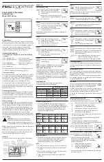
FUNCTIONAL DESCRIPTION
4
5
1. Laser window
2. Nameplate
3. Trigger
4. Display
5. Mode/Set/Alarm Buttons
6. Battery indicator
7. Hold indicator
8. Laser active indicator
9. Trigger lock indicator
10. Alarm indicator
11. °C or °F indicator
12. Primary measurement
13. Secondary measurement
14. Mode indicator
7
8
9
12
13
14
10
6
11
2
3
1
2
SYMBOLOGY
Volts
Direct
Current
CAUTION
Laser Light -
Do Not Stare Into Beam
Laser
Product
Avoid Exposure: Laser Radiation Is
Emitted
From
Aperture
To reduce the risk of injury, user must
read operator's manual.
ASSEMBLY
WARNING
Recharge only with the charger
specifi ed for the battery. For spe-
cifi c charging instructions, read the operator’s
manual supplied with your charger and battery.
Inserting/Removing the Battery
To
remove
the battery, push in the release buttons
and pull the battery pack away from the tool.
To
insert
the battery, slide the pack into the body
of the tool. Make sure it latches securely into place.
Selecting Celsius or Fahrenheit
To set the temperature scale, pull the trigger and
then press the SET button three times. Press the
buttons above the up and down arrows to toggle
between °C and °F. Wait 5 seconds for the setting
to save and exit.
Setting the Laser Lock
To turn the laser on and off, pull the trigger and then
press the SET button four times. Press the buttons
above the up and down arrows to toggle between
ON and OFF. Wait 5 seconds for the setting to save
and exit.
Distance to Spot: 12:1
—— Center of Spot
– – – Laser pointer (approx. 3/4" above center of spot)
Spot size at distance indicated
At 5' away, spot is 5" in diameter
At 3' away, spot is 3" in diameter
At 1' away, spot is 1.5"
in diameter
NOTE:
A quick change in
temperature (>10°F) af-
fects the meter’s readings.
Allow the meter to reach
ambient temperature be-
fore use (5 to 30 minutes,
depending on temperature
change).
MAINTENANCE
WARNING
To reduce the risk of injury, always
unplug the charger and remove the
battery pack from the charger or tool before
performing any maintenance. Never disassemble
the tool, battery pack or charger. Contact a
MILWAUKEE service facility for ALL repairs.
Maintaining Tool
Keep your tool, battery pack and charger in good re-
pair by adopting a regular maintenance program. Af-
ter six months to one year, depending on use, return
the tool, battery pack and charger to A MILWAUKEE
service facility for:
• Lubrication
• Mechanical inspection and cleaning (gears, spin-
dles, bearings, housing, etc.)
• Electrical inspection (battery pack, charger, motor)
• Testing to assure proper mechanical and electrical
operation
If the tool does not start or operate at full power with
a fully charged battery pack, clean the contacts on
the battery pack. If the tool still does not work prop-
erly, return the tool, charger and battery pack, to a
MILWAUKEE service facility for repairs.
Cleaning the Lens
Blow off loose particles with clean compressed
air. Carefully wipe the suface with a cotton swab
moistened with water. Using a second cotton swab,
dry completely.
WARNING
To reduce the risk of personal in-
jury and damage, never immerse
your tool, battery pack or charger in liquid or
allow a liquid to fl ow inside them.
Cleaning
Clean dust and debris from vents. Keep handles
clean, dry and free of oil or grease. Use only mild
soap and a damp cloth to clean, since certain clean-
ing agents and solvents are harmful to plastics and
other insulated parts. Some of these include gasoline,
turpentine, lacquer thinner, paint thinner, chlorinated
cleaning solvents, ammonia and household deter-
gents containing ammonia. Never use
fl
ammable or
combustible solvents around tools.
Repairs
For repairs, return the tool to the nearest service
center.
ACCESSORIES
WARNING
Always remove battery pack before
changing or removing accesso-
ries. Only use accessories specifi cally recom-
mended for this tool. Others may be hazardous.
For a complete listing of accessories, go online to
www.milwaukeetool.com or contact a local distributor.
OPERATION
Scanning Object Temperature
1. Pull and hold the trigger for at least 2 seconds and
scan the surface temperature of an object. A laser
pointer is used for aiming on the
area being scanned.
NOTE:
The object should be larger
than the spot being scanned. If
not, readings will be affected. See
Distance-To-Spot for necessary
object size.
2. As you continue to hold the trigger,
the icon
is displayed along with
the primary measurement (surface
temperature) and secondary mea-
surement (maximum, minimum,
average, or differential tempera-
ture) readings.
3. Release the trigger. HOLD is displayed until the
screen shuts off in about ten seconds.
Setting the Trigger Lock
To turn the trigger lock on and off, pull the trigger and
then press the SET button
fi
ve times. Press the
buttons above the up and down arrows to toggle
between ON and OFF. Wait 5 seconds for the
setting to save and exit.
Temperature Alarm
Press the ALARM button to turn on the
alarm function. The bell icon is dis-
played. If the temperature reading is
outside the preset range, the tem-
perature reading will
fl
ash.
Setting Preset Range
for the Alarm
1. To set the alarm range, pull the trig-
ger and then press the SET button.
Repeat to toggle between HI and
LO settings.
2. Press the up or down arrow soft
keys to toggle between tempera-
tures.
Wait 5 seconds for the ranges to
save and exit.
Low Battery
When the Battery icon is down to a
single bar, change the battery.
Mode
Description
MAX
Displays maximum temperature mea-
sured during a continuous reading
MIN
Displays minimum temperature mea-
sured during a continuous reading
AVG
Displays average temperature of last 20
measurements during a continuous reading
DIF
Displays the difference between MAX
and MIN during a continuous reading