21
There a re three leve ls o f calibration th at ca n b e
performed. Use the appropriate calibration routine
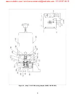
for you r requirement. For a ll r outines, reference
Figure 10.
4.8.1.1 Calibration A
Calibration A is performed to synchronize the ECC
with the pump. Calibration A is performed when:
•
Replacing any components in the position
feedback assembly. This includes the
nylon worm gear/driver, the potentiometer,
and/or the potentiometer gear.
•
Adding or removing reverse action jump-
ers (Section 3).
1. Tools needed for calibration A:
a) Digital volt meter (DVM) or equivalent with
resistance, 5 VDC, and 20 mA.
b) 4-20 mA (1-5 VDC) source and 115 or 220
VAC source
c) Precision screwdriver to a djust potentiom-
eters
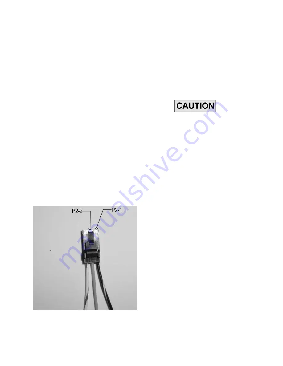
Figure 14. Potentiometer Connector P2 Pins 1
and 2
d) Tool kit
2. Preparation:
a) All new components should be replaced.
b) Insure pump is set to 0% setting.
c) Remove AC power.
d) Remove cover from ECC.
VOLTAGE SELECTOR SWITCH
SW1
LOCATED ON TOP OF THE CIRCUIT
BOARD MUST BE SET TO THE VOLT-
AGE LISTED ON YOUR DATA PLATE
(FIGURES 1 OR 2) , OR DAM AGE TO
MOTOR WILL RESULT.
e) Ensure voltage selector switch is set to 115
VAC or 230VAC as indicated on data plate
(Section 2).
f) If circuit board has be en replaced ensure
DIP switche s SW2 and SW3 are set as
needed for proper operation (Section 2).
g) Remove ECC from pump.
3. Remove PCB (Paragraph 4.4.1) to gain access
to feedback potentiometer.
4. Remove P2 and connect DVM between P2 pin
1 and P2 pin 2 (Figure 14). Loosen screws to
potentiometer to allow movement of potentiom-
eter gear without moving nylon worm gear. Set
potentiometer to 1.5K ohms ±100 ohms for Mil-
royal B, C, and Macroys, 0.87 ohms ±0.1 ohms
for mRoys a nd 1 .3 oh ms ±0 .1 ohm s for
Maxroys and Milroyal D E CCs and re-tighten
potentiometer screws. This sets the resistance
of the potentiometer.
5. Install PCB ( Paragraph 4 .4.2) a nd pe rform
remaining adjustments.
www.motralec.com / [email protected] / 01.39.97.65.10


