20
4.7.2 Installation of Motor
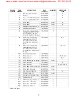
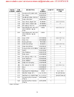
1. Mount motor to base (10) and secure with four
mounting screws (50).
2. Connect motor wires to J1.
3. Remove wo rm ge ar (1 90) fr om o ld m otor.
Carefully r emove spring p in (200) w ith 3/ 32
punch without damage to worm gear (190).
4. Slide wo rm ge ar (190) o ver ne w mo tor sh aft
and a lign sha ft h oles to ge ar hole s. Bein g
careful not to damage nylon worm gear, press
spring pin ( 200) through holes in g ear a nd
shaft with 3/32 punch. Place pin equal distance
from both sides of gear.
5. Attach adapter plate (60) to motor and secure
with two screws (140). O ne screw (140) also
mounts capacitor (65) to adapter plate.
6. Apply a very small amount of lithium grease (if
needed) to motor shaft nylon worm gear. Motor
shaft may have grease from previous mainte-
nance.
7. Reposition feedback potentiometer (Paragraph
4.5.2, Steps 1 & 2).
8. Position wirin g to J1 a s noted p reviously an d
attach two cable ties.
9. Install PCB (Paragraph 4.4.2, Steps 1 and 2).
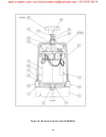
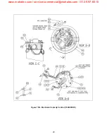
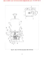
10. On mRoy A and B ECCs slide drive shaft (Fig-
ure 16 and 17, item 910) over bottom of motor
shaft an d align mounting ho les. Pre ss sp ring
pin (920) through both holes with 3/16 punch.
Place pin equ al d istance from both sides of
gear.
11. Slide gear removed previously from bottom of
motor shaft over new mo tor shaft. Align shaft
holes to gear holes. Being careful not to dam-
age ge ar, pr ess spring pin th rough holes in
gear and shaft with 1/8 punch. Place pin equal
distance from both sides of gear.
12. Apply lithium grease to gear above and mount
gear box to ECC with four screws (mRoy A and
B has no gear box).
13. Mount ECC to pump. Connect ECC to pump
bracket with four bolts/screws.
14. Connect power to ECC.
15. Perform calibration A.
4.8 ECC CALIBRATION
WARNING
YOU WILL BE MAKING ADJUSTMENTS
TO THE ECC
CONTROL CIRC UIT
BOARD WHILE IT IS POWERED UP.
THIS CONTROL BOAR D IS POWER ED
BY POTEN
TIALLY
DANGEROUS
VOLTAGE (1 15 OR 230 V AC). THE
CALIBRATION PROCED URE IS TO BE
PERFORMED ONLY BY QUAL
IFIED
PERSONNEL FAMILIAR WIT
H THE
HAZARDS INHERENT WORKING NEAR
HIGH VOLT AGES. MILTON ROY
ASSUMES NO RESPONSIBILITIES FOR
DAMAGE TO EQUIPMENT OR INJU RY
TO P ERSONNEL WH ILE PER FORMING
THIS CALIBRATION PROCEDURE.
NOTE
ECCs ar e ca librated at the fa ctory and
usually do no t ne ed to be calibrated ini-
tially.
4.8.1 Calibration Routines
The Milton Roy ECC has nine adjustment potenti-
ometers. Th ese p otentiometers adjust the ECC's
span and zero travel, lower and upper travel limits,
feedback ze ro, feed back sp an, contr ol of fset,
range of fset, an d feed back of fset. Co ntrol of fset,
range of fset, and feedback offset will only be
adjusted d uring a co mplete calibr ation pr ocedure
(calibration C). These three adjustments are usally
not changed.
Before calibration is pe rformed set-up the voltage
selector switch , SW1(Paragraph 2 .6.4), input sig-
nal SW2(Pa ragraph 2.6.2) , and feed back ou tput
signal SW3( Paragraph 2 .6.3).
Use o f t he fe ed-
back out put signa l is opt ional and needs set
only if it will be used.
www.motralec.com / [email protected] / 01.39.97.65.10


