background image

Connection to the gas supply, or
conversion from one type of gas to
another should only be undertaken
by an approved gas fitter, who is
responsible for correct functioning of
the appliance when installed. Every
appliance should have its own
isolating valve.

The gas connection must be
installed so that connection can be
made either from inside or outside
the kitchen unit, and the isolating
valve must be easily accessible and
visible (by opening one of the
kitchen unit doors, if necessary).

Check with your local gas supplier
about the type of gas and its
calorific value, and compare this
information with the type of gas
quoted on the appliance data plate.

This appliance is set up for connection
to natural gas.
See adhesive label on the appliance:
G = NG (natural gas)
LP = ULPG (Propane/Butane)

Jets are supplied for conversion to
ULPG (Propane/Butane) gas.

If the appropriate jets have not been
supplied with the appliance you will
need to contact your Chartered Agent
or the Technical Service Department.

Conversion to another type of gas is
described under the relevant Section.

Gas connection

40

Summary of Contents for CS 1011

Page 1: ...allation instructions Gas cooktops CS 1011 To avoid the risk of accidents or damage to the appliance it is essential to read these instructions before it is installed and used for the first time M Nr 07 235 550 en AU NZ ...

Page 2: ...hose specified on the appliance It is however set up for connection to the gas and electricity supplies in the countries specified For use in other countries please contact the Miele Spare Parts Department or Miele Customer Contact Centre in your country 2 ...

Page 3: ...ng the flame and switching off 16 In operation indicator and Residual heat indicator 18 Pans 19 Wok ring 19 Safety features 20 Cleaning and care 21 General notes 21 Stainless steel surfaces 22 Pan support control knob 22 Burner 23 Problem solving guide 24 Optional accessories 26 Safety instructions for installation 27 Safety clearances 28 Appliance and building in dimensions 30 Preparing the workt...

Page 4: ...iance 37 Removing the appliance 37 General installation tips 38 Electrical connection 39 Gas connection 40 Conversion to another type of gas 42 Jet table 42 Changing the jets 43 To change the main jet 43 To check the first intake of air 45 To change the small jets 46 After changing the jets 47 After sales service data plate 48 Contents 4 ...

Page 5: ...Cooktop aWok burner bPan support cControl knob dDisplay Display eIn operation indicator fResidual heat indicator Guide to the appliance 5 ...

Page 6: ...Burner gInner burner cap hOuter burner cap iBurner ring jBurner head kIgnition safety device lIgnitor mBurner base Guide to the appliance 6 ...

Page 7: ... as well as a range of optional ones are available to order see Optional accessories Wok ring The Wok ring supplied with your appliance can be used in instances where extra stability is required It is particularly suitable for Woks with a rounded base Guide to the appliance 7 ...

Page 8: ... ensure that new users are familiar with the content Pass them on to any future owner Correct use This appliance is intended for domestic use only and must be used as described in these instructions Any other usage is not permitted and could be dangerous The manufacturer cannot be held liable for damage resulting from incorrect or improper use or operation This appliance is not intended for use by...

Page 9: ...away from the appliance at all times Do not store anything which might arouse a child s interest in storage areas above or next to the appliance Otherwise they could be tempted into climbing onto the appliance with the risk of burning themselves Keep all pans out of reach of children Danger of burning or scalding Turn pan handles inwards away from the edge of the cooktop Packaging e g cling film p...

Page 10: ...plate correspond with the on site electricity supply otherwise the appliance could be damaged Consult a qualified electrician if in any doubt Do not connect the appliance to the mains electricity supply by a multi socket unit or an extension lead These do not guarantee the required safety of the appliance e g danger of overheating For safety reasons this appliance may only be used when it has been...

Page 11: ... be covered by the guarantee Correct usage The appliance is hot when in use and remains hot for quite a while after being switched off Do not touch it whilst it could still be hot For added protection it is advisable to use heat resistant pot holders or gloves when using the appliance Ensure that they do not come into contact with the flames Do not use large cloths tea towels or similar as the end...

Page 12: ...r tthis appliance Do not use the appliance as a resting place for anything else The article could melt or catch fire if residual heat is still present or if the appliance is switched on by mistake Do not cover the appliance e g with a cloth kitchen foil etc This could be a fire hazard if the appliance is switched on by mistake Remove splashes of fat and other food debris from the surface as soon a...

Page 13: ...emperature Some foods may contain micro organisms which are only destroyed by thorough cooking at a sufficiently high temperature for long enough Therefore when cooking or reheating food such as poultry it is particularly important that the food is completely cooked through If in doubt select a longer cooking or reheating time Spray canisters aerosols and other inflammable substances must not be s...

Page 14: ...erials which if handled or disposed of incorrectly could be potentially hazardous to human health and to the environment They are however essential for the correct functioning of your appliance or machine Therefore please do not dispose of your old machine or appliance with your household waste Please dispose of it at your local community waste collection recycling centre and ensure that it presen...

Page 15: ...water and a small amount of washing up liquid applied with a soft sponge Dry all parts thoroughly after cleaning and then reassemble the burner see Cleaning and care burner Clean the stainless steel trough with a damp cloth and then wipe dry Metal components have a protective coating which may give off a slight smell when heated up for the first time The smell and any vapours will dissipate after ...

Page 16: ...highest setting Strong flame 5 o clock position The outer burner is switched off the inner burner operates at the highest setting Weakest flame The outer burner is switched off the inner burner operates at the lowest setting The burner can only be switched on by pushing in the control and turning it anti clockwise It is switched off by turning the control clockwise The outer flame ring can only be...

Page 17: ...it does not spread out beyond the sides of the pan As the outer part of the flame is much hotter than the centre the tips of the flames should stay beneath the pan base Flame tips which extend beyond the sides of the pan merely warm up the air in the room and can also damage pan handles and increase the risk of injury To move from the high to the low setting turn the control anti clockwise until i...

Page 18: ...s up The in operation indicator goes out when the gas cooktop is switched off The residual heat indicator remains on until the gas cooktop is cool enough to touch Do not touch or place any heat sensitive objects on the gas cooktop while the residual heat indicator is still on Danger of burning and fire If the display is flashing this shows there is a fault See section Problem solving guide Operati...

Page 19: ...the appliance must always be used Never place a pan on the burner itself Use the correct sized pans for your appliance A pan which is too small will be unstable on the pan support If the pan diameter is too large flames can spread out to the sides and damage or burn the worktop wall claddings or surrounding units and also parts of the cooktop The manufacturer cannot be held liable for this type of...

Page 20: ... unsuccessful the supply of gas to the burner will be cut off To use the burner again turn the control clockwise to the ß position and then switch it back on as normal Safety cut out If a burner has been used for an unusually long period approx 4 hours it will switch off automatically To use the burner again turn the control clockwise to the ß position and then switch it back on as normal Safety f...

Page 21: ...soon as possible to avoid the risk of corrosion To avoid damaging the surface or your cooktop do not use cleaning agents containing soda alkaline ammonia acids or chlorides cleaning agents containing descaling agents stain or rust removers abrasive cleaning agents e g powder cleaners and cream cleaners solvent based cleaning agents dishwasher cleaner grill and oven cleaners glass cleaning agents h...

Page 22: ...rint These areas should be only cleaned with a solution of warm water and a small amount of washing up liquid applied with a soft sponge A conditioning agent for stainless steel can be used after cleaning to help keep your appliance looking good see Optional accessories Apply sparingly with a soft cloth following the instructions on the packaging Pan support control knob Remove the pan support Cle...

Page 23: ...it will not spark After cleaning dry all surfaces with a clean cloth Make sure that the flame slits are clean and completely dry The surfaces of the two burner caps will become more matt with time This is quite normal and will not affect the operation of the cooktop Reassemble the burner After cleaning the burner it must be reassembled in the correct order Place burner head j on to burner base m s...

Page 24: ...then operate the appliance as normal the in operation indicator is flashing There is no supply of gas Turn all the controls clockwise to position ß You can then operate the appliance as normal If the problem persists disconnect the appliance from the electricity supply for a few seconds the burner does not ignite after several attempts Disconnect the appliance from the electricity supply for a few...

Page 25: ...has tripped If it has contact a qualified electrician or the Miele Customer Contact Centre food deposits have lodged themselves between the ignitor and the burner cap Remove any food deposits carefully see Cleaning and care food deposits have lodged themselves on the ignition safety device Remove any food deposits carefully see Cleaning and care For safety reasons you may not be able to re ignite ...

Page 26: ...nding on country or from the Miele Spare Parts Department see back cover Ceramic and stainless steel cooktop cleaner 250 ml Removes heavy soiling limescale deposits and light discolouration Stainless steel conditioning agent 250 ml Removes water marks flecks and finger prints Helps keep the cooktop looking good for longer Optional accessories 26 ...

Page 27: ...ryer must not be installed directly next to a gas cooktop as the gas flames could ignite the fat in the fryer It is essential to maintain a distance of at least 288 mm between these two appliances A gas cooktop may not be built in over a fridge fridge freezer freezer dishwasher washing machine or tumble dryer It can be installed above an oven The worktop must be at least 40 mm thick Ensure that th...

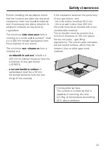
Page 28: ...m must be maintained between them and the cooktop below When two or more appliances are installed together below a rangehood e g a gas cooktop and an induction cooktop combiset which have different safety clearances given in the installation instructions you should select the greater clearance of the two Side rear clearances to the cooktop Ideally the cooktop should be installed with plenty of spa...

Page 29: ...rner AS 5601 non combustible surface or splashback shall be a 50 mm horizontal distance from the rear edge of the cooktop If the clearance between the periphery of any gas burner and the side wall is less than 300 mm the rear wall is less than 200 mm the walls must be protected with a non combustible material The protection must be extended a minimum distance of 150 mm above the burner refer gas f...

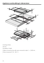
Page 30: ...aSpring clamps bFront cBuilding in depth dMains connection box with mains connection cable L 2 000 mm eGas connection R 1 2 ISO 7 1 Appliance and building in dimensions 30 ...

Page 31: ...ht or left of the appliance See Safety clearances Seal the cut surfaces with a suitable heat resistant sealant to avoid swelling caused by moisture The materials used must be heat resistant If during installation you find that the seals on the corners of the frame are not flush with the worktop surface the corner radius ß R4 can be carefully scribed to fit Preparing the worktop 31 ...

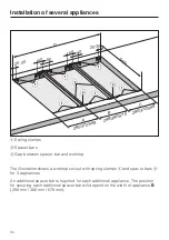
Page 32: ...ances When installing three appliances the width of the cut out required D is calculated by adding dimensions A B and C A appliance width 288 mm or 380 mm or 576 mm less 8 mm B appliance width 288 mm or 380 mm or 576 mm C appliance width 288 mm or 380 mm or 576 mm less 8 mm D width of worktop cut out When installing more than three appliances for each additional appliance add the relevant applianc...

Page 33: ...s 8 B Appliance width C Appliance width less 8 D Worktop cut out 280 288 280 848 280 380 372 1032 280 576 568 1424 372 288 280 940 372 380 372 1124 372 576 568 1516 568 288 280 1136 568 380 372 1320 568 568 1136 All dimensions are given in mm Installation of several appliances 33 ...

Page 34: ...er bars b for 3 appliances An additional spacer bar is required for each additional appliance The position for securing each additional spacer bar will depend on the width of appliance B 288 mm 380 mm 576 mm Installation of several appliances 34 500 A B C b a a 25 30 D a a a a 25 30 280 372 568 280 372 568 288 380 576 50 50 50 50 c c ...

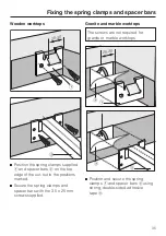
Page 35: ...cure the spring clamps and spacer bars with the 3 5 x 25 mm screws supplied Granite and marble worktops The screws are not required for granite or marble worktops Position and secure the spring clamps a and spacer bars b using strong double sided adhesive tape c Fixing the spring clamps and spacer bars 35 25 30 a b 25 30 a c b c ...

Page 36: ...e side edges and the lower edges of the spring clamps with silicone Then fill gap d between the spacer bars and the worktop with silicone from the tube supplied Fixing the spring clamps and spacer bars 36 b d a ...

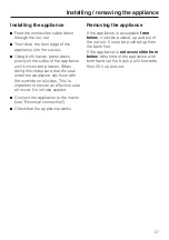
Page 37: ...rktop on all sides This is important to ensure an effective seal all round Do not use sealant Connect the appliance to the mains see Electrical connection Check that the appliance works Removing the appliance If the appliance is accessible from below it can be pushed up and out of the cut out It must be pushed up from the back first If the appliance is not accessible from below take hold of the ap...

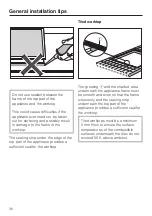
Page 38: ...the applinace provides a sufficient seal for the worktop Tiled worktop The grouting a and the shaded area underneath the appliance frame must be smooth and even so that the frame sits evenly and the sealing strip underneath the top part of the appliance provides a sufficient seal for the worktop Tiled worktops must be a minimum 5 mm thick to ensure the surface temperatures of the combustible surfa...

Page 39: ...cessible and visible The data plate gives the necessary data for connection WARNING THIS APPLIANCE MUST BE EARTHED Important The wires in the mains lead are coloured in accordance with the following code Green yellow earth Blue neutral Brown live As the colours of the wires in the mains lead of this appliance may not correspond with the coloured markings identifying the terminals in your plug proc...

Page 40: ...g one of the kitchen unit doors if necessary Check with your local gas supplier about the type of gas and its calorific value and compare this information with the type of gas quoted on the appliance data plate This appliance is set up for connection to natural gas See adhesive label on the appliance G NG natural gas LP ULPG Propane Butane Jets are supplied for conversion to ULPG Propane Butane ga...

Page 41: ...st be set by the approved gas fitter as shown on the data plate Natural gas 1 0 kPa ULPG Propane Butane 2 75 kPa Disconnect gauge and screw in the test point screw The Gas Regulator must be set with the largest burner operating at maximum setting Once the gas cooktop has been installed it is essential to check that neither the gas pipe nor the electricity cable is in contact with hot parts of the ...

Page 42: ...jets and the small burner jets have to be changed Nominal rating at high setting Gas type MJ h NG ULPG 15 15 Nominal ratings for ULPG are based on propane gas Nominal rating at low setting Gas type MJ h NG ULPG 5 99 5 89 Nominal ratings for ULPG are based on propane gas Screw in the new jets according to the following table Jet table Main jet C Small jet C NG 1 8 34 1 10 0 42 ULPG 1 05 7 0 68 0 25...

Page 43: ...rol knob off Loosen screws w and remove the upper section of the appliance Remove the top from the cooktop carefully Make sure the in operation and residual heat indicator module a which is located beneath the cooktop isn t detached during this process To release the residual heat module press both snap in hooks b inwards Whilst counterholding it in place with an SW 13 spanner unscrew the main jet...

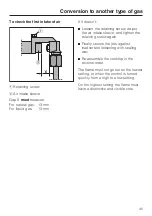
Page 44: ...h an SW 12 spanner remove screw fitting b from fitting a with another SW 12 spanner Remove jet disc d from fitting a and replace with the correct jet disc see jet table Adjust air intake sleeve e until the two vents f have a 2 mm gap as illustrated Reassemble the parts in the reverse order and check for leaks by operating the burner without the upper part of the cooktop in place use a match to ign...

Page 45: ...take sleeve and tighten the retaining screw again Finally secure the jets against inadvertent loosening with sealing wax Re assemble the cooktop in the reverse order The flame must not go out on the lowest setting or when the control is turned quickly from a high to a low setting On the highest setting the flame must have a distinctive and visible core Conversion to another type of gas 45 ...

Page 46: ...g for liquid gas 0 68 Using a small screwdriver unscrew the two small jets a and b in the gas fitting Pull out the jets with a pair of pliers Fit the correct jets securely see jet table Finally secure the jets against inadvertent loosening with sealing wax Conversion to another type of gas 46 ...

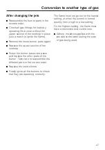
Page 47: ... and replace the other parts of the burner Take care to reassemble the different parts in the correct order Replace the control knob Finally ignite all the burners to check that they are operating correctly The flame must not go out on the lowest setting or when the control is turned quickly from a high to a low setting On the highest setting the flame must have a distinctive and visible core Adhe...

Page 48: ...ate Please quote these data together with the model description and serial number when contacting the Miele Customer Contact Centre Space in which to adhere the extra data plate supplied with the appliance Ensure that the model number is the same as the one on the front of these operating instructions After sales service data plate 48 ...

Page 49: ...49 ...

Page 50: ...50 ...

Page 51: ...51 ...

Page 52: ...Alteration rights reserved 5108 M Nr 07 235 550 02 ...

Reviews: