


Service manual
25
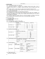
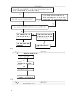
11.2. Protection
11.2.1. 3 minutes delay at restart for compressor.
11.2.2. Temperature protection of compressor top, compressor stops when the temp. of top of
compressor is more than 115
℃
, compressor runs when the temp. of top of compressor is less than
100
℃
.
11.2.3. Voltage protection, unit stop when the voltage is more than 260V and less than 175V.
11.2.4. Inverter module Protection, Inverter module Protection itself has a protection function against
current, voltage and temperature.
11.2.5. Sensor protection at open circuit and breaking disconnection
11.2.6. Fan Speed is out of control. When Indoor Fan Speed is too high (higher than 2100RPM) or too
low (lower than 300RPM), the unit stops and LED displays failure information and can’t return
to
normal operation automatically.
11.2.7. Cross Zero signal error warning. If there is no Cross Zero signals in 4 minutes, the unit stops
and LED displays failure information and can’t return to normal operation automatically.
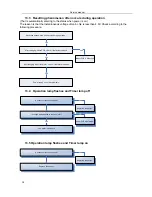
11.3. Fan-only mode
Fan speed is high/mid/low/ Auto
11.4. Cooling mode
11.4.1. The 4-way valve is closed at cooling mode.
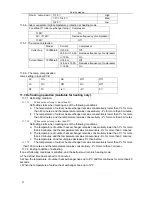
11.4.2. The action of the compressor and the outdoor fan:
Condition
T=Indoor Temp.
Compressor Outdoor
fan
T> Ts+1
On
On
Room temp. up
T<Ts+1 Off
Off
T> Ts
On
On
Room temp. down
T<Ts Off
Off
11.4.3 Auto fan at cooling mode:
Condition
T=Indoor Temp.-Setting Temp.
Indoor fan speed
T<1.5
℃
Low
1.5
℃
<T<4
℃
Mid.
Room temp. up
T>4
℃
High
T> 3
℃
High
1
℃
<T<3
℃
Mid.
Room temp. down
T<1
℃
Low
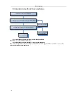
11.4.4 Anti-freezing control to indoor evaporator at cooling mode( T: evaporator temp. )
Evaporator
Temp.
Compressor
0
℃
<T< 4
℃
Decrease frequency of compressor
T< 0
℃
Off
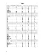
11.4.5 Current protection
Model
Current
Compressor
I>18 A
Off
14.5A<I<18A
Decrease frequency of
compressor
Current up
MSH-18HRIN1
I< 12.0A
On
I>17.5 A
Off
14.0A<I<17.5A
Decrease frequency of
compressor
Current down
MSH-18HRIN1
I< 11.5A
On
11.4.6 Rated capacity test
Set mode to cooling mode
Summary of Contents for MSV1-09HRDN1
Page 1: ...Cover MSV1 09HRDN1 MSV1 12HRDN1...
Page 4: ......
Page 11: ...Service manual 5 Refrigerant cycle diagram 7...
Page 14: ...Service manual 7 1 2 Indoor main PCB 10...
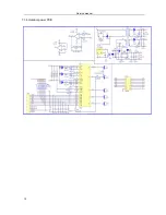
Page 15: ...Service manual 7 1 3 Outdoor main PCB 11...
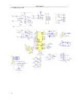
Page 16: ...Service manual 7 1 4 Outdoor power PCB 12...
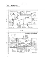
Page 17: ...Service manual 7 2 Wiring diagram 7 2 1 MSV1 09HRDN1 MSV1 12HRDN1 13...


