Electrical Control Function
192
Electrical Control System
01
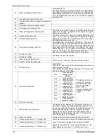
Indoor unit capacity demand code
Actual data*HP*10
If capacity demand code is higher than 99, the digital display
tube will show single digit and tens digit. (For example, the
digital display tube show “5.0”,it means the capacity demand
is 15. the digital display tube show “60”,it means the capacity
demand is 6.0)
02
Amendatory capacity demand code
03
The frequency after the capacity requirement
transfer
04
The frequency after the frequency limit
05
The frequency of sending to 341
06
Indoor unit evaporator outlet temp.(T2)
If the temp. is lower than 0 degree, the digital display tube will
show “0”.If the temp. is higher than 70 degree, the digital
display tube will show “70”.
07
Condenser pipe temp.(T3)
If the temp. is lower than -9 degree, the digital display tube will
show “-9”.If the temp. is higher than 70 degree, the digital
display tube will show “70”. If the indoor unit is not connected,
the digital display tube will show: “
――
”
08
Outdoor ambient temp.(T4)
09
Compressor discharge temp.(Tp)
The display value is between 30~120 degree. If the temp. is
lower than 30 degree, the digital display tube will show “30”.If
the temp. is higher than 99 degree, the digital display tube will
show single digit and tens digit. (For example, the digital
display tube show “0.5”,it means the compressor discharge
temp. is 105 degree. the digital display tube show “1.6”,it
means the compressor discharge temp. is 116 degree)
10
AD value of current
The display value is hex number.
11
AD value of voltage
12
Indoor unit running mode code
Off:0, Fan only 1,Cooling:2, Heating:3, Forced cooling:4
13
Outdoor unit running mode code
14 EXV
open
angle
Actual data/4.
If the value is higher than 99, the digital display tube will show
single digit and tens digit.
For example ,the digital display tube show “2.0”,it means the
EXV open angle is 120×4=480p.)
15 Frequency
limit
symbol
Bit7
Frequency limit
caused by IGBT
radiator
The display value is hex
number. For example,
the digital display tube
show 2A,then Bit5=1,
Bit3=1, Bit1=1.
It means frequency limit
caused by T4,T3 and
current.
Bit6
Frequency limit
caused by PFC
Bit5
Frequency limit
caused by T4.
Bit4
Frequency limit
caused by T2.
Bit3
Frequency limit
caused by T3.
Bit2
Frequency limit
caused by Tp.
Bit1
Frequency limit
caused by current
Bit0
Frequency limit
caused by voltage
16
DC fan motor speed
17
IGBT radiator temp.(Reserved)
The display value is between 13~120 degree. If the temp. is
lower than 13 degree, the digital display tube will show “13”.If
the temp. is higher than 99 degree, the digital display tube will
show single digit and tens digit. (For example, the digital
display tube show “0.5”,it means the IGBT radiator temp. is
105 degree. the digital display tube show “1.6”,it means the
IGBT radiator temp. is 116 degree)
18
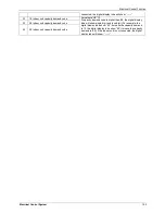
Indoor unit number
The indoor unit can communicate with outdoor unit well.
19
Condenser pipe temp. of 1# indoor unit
If the temp. is lower than 0 degree, the digital display tube will
show “0”.If the temp. is higher than 70 degree, the digital
display tube will show “70”. If the capacity demand is 0, , the
digital display tube will show “0. If the indoor unit is not
20
Condenser pipe temp. of 2# indoor unit
21
Condenser pipe temp. of 3# indoor unit
Summary of Contents for mcd-24hrdn1
Page 1: ...DC INVERTER SERIES Service Manual 2013 LIS B 1306...
Page 2: ......
Page 4: ......
Page 15: ...Dimensions 11 2 Dimensions...
Page 16: ...Service Space 12 3 Service Space...
Page 17: ...Wiring Diagrams 13 4 Wiring Diagrams MCA2 12HRDN1 Q MCA2 18HRDN1 Q...
Page 21: ...Field Wiring 17 10 Field Wiring MCA2 12HRDN1 Q MCA2 18HRDN1 Q...
Page 22: ...Field Wiring 18 MCA2 12HRDN1 Q MCA2 18HRDN1 Q...
Page 28: ...Service Space 26 Four way Cassette Type 3 Service Space 1000mm 1000mm 1000mm 1000m m...
Page 29: ...Wiring Diagrams Four way Cassette Type 27 4 Wiring Diagrams MCC 24HRDN1 Q MCC 30HRDN1 Q...
Page 30: ......
Page 31: ...Wiring Diagrams Four way Cassette Type 21 MCC 36HRDN1 Q MCC 48HRDN1 Q MCC 60HRDN1 R...
Page 36: ...Field Wiring 26 Four way Cassette Type 10 Field Wiring Wiring chart...
Page 43: ...Service Space Super Slim Cassette Type 33 3 Service Space 1000mm 1000mm 1000mm 1000m m...
Page 58: ...Wiring Diagrams 48 Duct Type MTB 36HWDN1 Q MTB 48HWDN1 Q MTB 60HWDN1 R...
Page 65: ...Field Wiring Duct Type 55 10 Field Wiring...
Page 66: ...Field Wiring 56 Duct Type Air conditioner link circuit For model 12 For model 18 60...
Page 72: ...Wiring Diagrams 62 Ceiling Floor Type MUB 18HRDN1 Q MUB 24HRDN1 Q MUB 30HRDN1 Q...
Page 79: ...Field Wiring Ceiling Floor Type 69 10 Field Wiring...
Page 80: ...Field Wiring 70 Ceiling Floor Type For model 12 For model 18 60...
Page 82: ......
Page 85: ...Features Console Type 75...
Page 86: ...Dimensions 76 Console Type 2 Dimensions MFA 12HRDN1 Q MFA 18HRDN1 Q...
Page 87: ...Service Space Console Type 77 3 Service Space...
Page 88: ...Wiring Diagrams 78 Console Type 4 Wiring Diagrams MFA 12HRDN1 Q MFA 18HRDN1 Q...
Page 93: ...Field Wiring Console Type 83 10 Field Wiring...
Page 94: ...Field Wiring 84 Console Type...
Page 97: ...Dimensions High Static Pressure Duct 87 2 Dimensions MHD 36HRDN1 Q MHD 48HRDN1 Q MHD 60HRDN1 R...
Page 104: ...Field Wiring 94 High Static Pressure Duct 10 Field Wiring...
Page 108: ...Service Space 98 3rd Generation Ceiling Floor Type 3 Service Space...
Page 114: ...Field Wiring 104 3rd Generation Ceiling Floor Type 9 Field Wiring MUE 48HRDN1 Q MUE 60HRDN1 R...
Page 118: ...Service Space 108 GA Floor standing Type 3 Service Space...
Page 122: ...Accessories 112 GA Floor standing Type 7 Accessories...
Page 124: ...Field Wiring 114 GA Floor standing Type 9 Field Wiring MFGA 24ARDN1 QC2...
Page 125: ...Field Wiring GA Floor standing Type 115 MFGA 36ARDN1 R MFGA 48ARDN1 R MFGA 60ARDN1 R...
Page 129: ...Dimensions Outdoor Units 119 New MOU 48HDN1 Q MOU 48HDN1 R MOU 60HDN1 R...
Page 133: ...Wiring Diagrams Outdoor Units 123 4 Wiring Diagrams MOU 12HDN1 Q MOU 18HDN1 Q...
Page 134: ...Wiring Diagrams 124 Outdoor Units MOU 24HDN1 Q 220075301400 MOU 24HDN1 Q 220075302030...
Page 135: ...Wiring Diagrams Outdoor Units 125 MOU 30HDN1 Q MOU 36HDN1 Q 220075501600...
Page 136: ...Wiring Diagrams 126 Outdoor Units MOU 36HDN1 Q 220075501990...
Page 137: ...Wiring Diagrams Outdoor Units 127 MOU 48HDN1 Q MOU 48HDN1 Q New Body...
Page 138: ...Wiring Diagrams 128 Outdoor Units MOU 36HDN1 R MOU 48HDN1 R MOU 60HDN1 R...
Page 139: ...Wiring Diagrams Outdoor Units 129 MOU 48HDN1 R MOU 60HDN1 R New Body...
Page 224: ...Troubleshooting 214 Electrical Control System 2 4 2 10 P0 malfunction...
Page 225: ...Troubleshooting Electrical Control System 215 2 4 2 11 P1 malfunction Only for 30K 60K...
Page 226: ...Troubleshooting 216 Electrical Control System 2 4 2 12 P2 malfunction Only for 30K 60K...
Page 227: ...Troubleshooting Electrical Control System 217 2 4 2 13 P3 malfunction...


