Additional refrigerant charge
Installation
173
8. Additional refrigerant charge
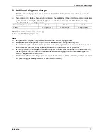
After the vacuum drying process is carried out, the additional refrigerant charge process need to be
performed.
The outdoor unit is factory charged with refrigerant. The additional refrigerant charge volume is decided
by the diameter and length of the liquid pipe between indoor and outdoor unit. Refer the following
formula to calculate the charge volume.
Diameter of liquid pipe (mm)
Φ
6.35
Φ
9.52
Φ
12.7
Formula
V=11g/m×(L-5) V=30g/m×(L-5) V=60g/m×(L-5)
V:
Additional refrigerant charge volume (g).
L :
The length of the liquid pipe (m).
Note:
Refrigerant may only be charged after performed the vacuum drying process.
Always use gloves and glasses to protect your hands and eyes during the charge work.
Use electronic scale or fluid infusion apparatus to weight refrigerant to be recharged. Be sure to avoid
extra refrigerant charged, it may cause liquid hammer of the compressor or protections.
Use supplementing flexible pipe to connect refrigerant cylinder, pressure gauge and outdoor unit. And
The refrigerant should be charged in liquid state. Before recharging, The air in the flexible pipe and
manifold gauge should be exhausted.
After finished refrigerant recharge process, check whether there is refrigerant leakage at the connection
joint part.(Using gas leakage detector or soap water to detect).
Summary of Contents for mcd-24hrdn1
Page 1: ...DC INVERTER SERIES Service Manual 2013 LIS B 1306...
Page 2: ......
Page 4: ......
Page 15: ...Dimensions 11 2 Dimensions...
Page 16: ...Service Space 12 3 Service Space...
Page 17: ...Wiring Diagrams 13 4 Wiring Diagrams MCA2 12HRDN1 Q MCA2 18HRDN1 Q...
Page 21: ...Field Wiring 17 10 Field Wiring MCA2 12HRDN1 Q MCA2 18HRDN1 Q...
Page 22: ...Field Wiring 18 MCA2 12HRDN1 Q MCA2 18HRDN1 Q...
Page 28: ...Service Space 26 Four way Cassette Type 3 Service Space 1000mm 1000mm 1000mm 1000m m...
Page 29: ...Wiring Diagrams Four way Cassette Type 27 4 Wiring Diagrams MCC 24HRDN1 Q MCC 30HRDN1 Q...
Page 30: ......
Page 31: ...Wiring Diagrams Four way Cassette Type 21 MCC 36HRDN1 Q MCC 48HRDN1 Q MCC 60HRDN1 R...
Page 36: ...Field Wiring 26 Four way Cassette Type 10 Field Wiring Wiring chart...
Page 43: ...Service Space Super Slim Cassette Type 33 3 Service Space 1000mm 1000mm 1000mm 1000m m...
Page 58: ...Wiring Diagrams 48 Duct Type MTB 36HWDN1 Q MTB 48HWDN1 Q MTB 60HWDN1 R...
Page 65: ...Field Wiring Duct Type 55 10 Field Wiring...
Page 66: ...Field Wiring 56 Duct Type Air conditioner link circuit For model 12 For model 18 60...
Page 72: ...Wiring Diagrams 62 Ceiling Floor Type MUB 18HRDN1 Q MUB 24HRDN1 Q MUB 30HRDN1 Q...
Page 79: ...Field Wiring Ceiling Floor Type 69 10 Field Wiring...
Page 80: ...Field Wiring 70 Ceiling Floor Type For model 12 For model 18 60...
Page 82: ......
Page 85: ...Features Console Type 75...
Page 86: ...Dimensions 76 Console Type 2 Dimensions MFA 12HRDN1 Q MFA 18HRDN1 Q...
Page 87: ...Service Space Console Type 77 3 Service Space...
Page 88: ...Wiring Diagrams 78 Console Type 4 Wiring Diagrams MFA 12HRDN1 Q MFA 18HRDN1 Q...
Page 93: ...Field Wiring Console Type 83 10 Field Wiring...
Page 94: ...Field Wiring 84 Console Type...
Page 97: ...Dimensions High Static Pressure Duct 87 2 Dimensions MHD 36HRDN1 Q MHD 48HRDN1 Q MHD 60HRDN1 R...
Page 104: ...Field Wiring 94 High Static Pressure Duct 10 Field Wiring...
Page 108: ...Service Space 98 3rd Generation Ceiling Floor Type 3 Service Space...
Page 114: ...Field Wiring 104 3rd Generation Ceiling Floor Type 9 Field Wiring MUE 48HRDN1 Q MUE 60HRDN1 R...
Page 118: ...Service Space 108 GA Floor standing Type 3 Service Space...
Page 122: ...Accessories 112 GA Floor standing Type 7 Accessories...
Page 124: ...Field Wiring 114 GA Floor standing Type 9 Field Wiring MFGA 24ARDN1 QC2...
Page 125: ...Field Wiring GA Floor standing Type 115 MFGA 36ARDN1 R MFGA 48ARDN1 R MFGA 60ARDN1 R...
Page 129: ...Dimensions Outdoor Units 119 New MOU 48HDN1 Q MOU 48HDN1 R MOU 60HDN1 R...
Page 133: ...Wiring Diagrams Outdoor Units 123 4 Wiring Diagrams MOU 12HDN1 Q MOU 18HDN1 Q...
Page 134: ...Wiring Diagrams 124 Outdoor Units MOU 24HDN1 Q 220075301400 MOU 24HDN1 Q 220075302030...
Page 135: ...Wiring Diagrams Outdoor Units 125 MOU 30HDN1 Q MOU 36HDN1 Q 220075501600...
Page 136: ...Wiring Diagrams 126 Outdoor Units MOU 36HDN1 Q 220075501990...
Page 137: ...Wiring Diagrams Outdoor Units 127 MOU 48HDN1 Q MOU 48HDN1 Q New Body...
Page 138: ...Wiring Diagrams 128 Outdoor Units MOU 36HDN1 R MOU 48HDN1 R MOU 60HDN1 R...
Page 139: ...Wiring Diagrams Outdoor Units 129 MOU 48HDN1 R MOU 60HDN1 R New Body...
Page 224: ...Troubleshooting 214 Electrical Control System 2 4 2 10 P0 malfunction...
Page 225: ...Troubleshooting Electrical Control System 215 2 4 2 11 P1 malfunction Only for 30K 60K...
Page 226: ...Troubleshooting 216 Electrical Control System 2 4 2 12 P2 malfunction Only for 30K 60K...
Page 227: ...Troubleshooting Electrical Control System 217 2 4 2 13 P3 malfunction...


