Troubleshooting
198
Electrical Control System
6
IPM module protection
☆
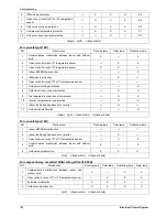
X X O E5
7
Open or short circuit of T3 or T4 temperature
sensor
☆
O X X E6
8
Outdoor unit voltage protection
☆
O X O P0
9
Compressor temperature protection
☆
X O X P1
10
Outdoor unit over-current protection
☆
☆
X
☆
P2
O(light) X(off)
☆
(flash at 5Hz)
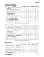
For console type(12K)
NO. Malfunction Running
lamp
Timer lamp
Defrosting lamp
1
Communication malfunction between indoor and outdoor
units.
X
☆
X
2
Open or short circuit of T1 temperature sensor
☆
X X
3
Open or short circuit of T2 temperature sensor
X
X
☆
4
Indoor EEPROM malfunction
☆
☆
X
5
IPM module protection
☆
X
☆
6
Open or short circuit of T3 or T4 temperature sensor
☆
☆
☆
7
Outdoor unit voltage protection
☆
☆
O
8
Outdoor unit over-current protection
☆
O O
9
Top temperature protection of compressor
☆
O X
10
Inverter compressor drive protection
☆
◎
X
11
Indoor fan Speed has been out of control.
☆
O
☆
12
Outdoor fan malfunction
X
☆
O
O(light) X(off)
☆
(flash at 5Hz)
◎
(flash at 0.5Hz)
For console type(18K)
NO. Malfunction Running
lamp
Timer lamp
Defrosting lamp
1
Indoor EEPROM malfunction
☆
☆
☆
2
Indoor fan Speed has been out of control.
☆
X
☆
3
Open or short circuit of T1 or T2 temperature sensor
☆
☆
X
4
Communication malfunction between indoor and outdoor
units.
X
☆
X
5
Outdoor unit malfunction
X
X
◎
X(off)
☆
(flash at 5Hz)
◎
(flash at 0.5Hz)
For compact 4-way cassette(18K)&ceiling & floor(18-30K)
NO. Malfunction Running
lamp
Timer
lamp
Defrosting lamp Alarm lamp
1
Communication malfunction between indoor and
outdoor units.
X
☆
X X
2
Open or short circuit of T1 or T2 temperature sensor
☆
X X X
3 Full-water
malfunction
X
X
X
☆
4
Outdoor unit malfunction
X
X
X
◎
X(off)
☆
(flash at 5Hz)
◎
(flash at 0.5Hz)
Summary of Contents for mcd-24hrdn1
Page 1: ...DC INVERTER SERIES Service Manual 2013 LIS B 1306...
Page 2: ......
Page 4: ......
Page 15: ...Dimensions 11 2 Dimensions...
Page 16: ...Service Space 12 3 Service Space...
Page 17: ...Wiring Diagrams 13 4 Wiring Diagrams MCA2 12HRDN1 Q MCA2 18HRDN1 Q...
Page 21: ...Field Wiring 17 10 Field Wiring MCA2 12HRDN1 Q MCA2 18HRDN1 Q...
Page 22: ...Field Wiring 18 MCA2 12HRDN1 Q MCA2 18HRDN1 Q...
Page 28: ...Service Space 26 Four way Cassette Type 3 Service Space 1000mm 1000mm 1000mm 1000m m...
Page 29: ...Wiring Diagrams Four way Cassette Type 27 4 Wiring Diagrams MCC 24HRDN1 Q MCC 30HRDN1 Q...
Page 30: ......
Page 31: ...Wiring Diagrams Four way Cassette Type 21 MCC 36HRDN1 Q MCC 48HRDN1 Q MCC 60HRDN1 R...
Page 36: ...Field Wiring 26 Four way Cassette Type 10 Field Wiring Wiring chart...
Page 43: ...Service Space Super Slim Cassette Type 33 3 Service Space 1000mm 1000mm 1000mm 1000m m...
Page 58: ...Wiring Diagrams 48 Duct Type MTB 36HWDN1 Q MTB 48HWDN1 Q MTB 60HWDN1 R...
Page 65: ...Field Wiring Duct Type 55 10 Field Wiring...
Page 66: ...Field Wiring 56 Duct Type Air conditioner link circuit For model 12 For model 18 60...
Page 72: ...Wiring Diagrams 62 Ceiling Floor Type MUB 18HRDN1 Q MUB 24HRDN1 Q MUB 30HRDN1 Q...
Page 79: ...Field Wiring Ceiling Floor Type 69 10 Field Wiring...
Page 80: ...Field Wiring 70 Ceiling Floor Type For model 12 For model 18 60...
Page 82: ......
Page 85: ...Features Console Type 75...
Page 86: ...Dimensions 76 Console Type 2 Dimensions MFA 12HRDN1 Q MFA 18HRDN1 Q...
Page 87: ...Service Space Console Type 77 3 Service Space...
Page 88: ...Wiring Diagrams 78 Console Type 4 Wiring Diagrams MFA 12HRDN1 Q MFA 18HRDN1 Q...
Page 93: ...Field Wiring Console Type 83 10 Field Wiring...
Page 94: ...Field Wiring 84 Console Type...
Page 97: ...Dimensions High Static Pressure Duct 87 2 Dimensions MHD 36HRDN1 Q MHD 48HRDN1 Q MHD 60HRDN1 R...
Page 104: ...Field Wiring 94 High Static Pressure Duct 10 Field Wiring...
Page 108: ...Service Space 98 3rd Generation Ceiling Floor Type 3 Service Space...
Page 114: ...Field Wiring 104 3rd Generation Ceiling Floor Type 9 Field Wiring MUE 48HRDN1 Q MUE 60HRDN1 R...
Page 118: ...Service Space 108 GA Floor standing Type 3 Service Space...
Page 122: ...Accessories 112 GA Floor standing Type 7 Accessories...
Page 124: ...Field Wiring 114 GA Floor standing Type 9 Field Wiring MFGA 24ARDN1 QC2...
Page 125: ...Field Wiring GA Floor standing Type 115 MFGA 36ARDN1 R MFGA 48ARDN1 R MFGA 60ARDN1 R...
Page 129: ...Dimensions Outdoor Units 119 New MOU 48HDN1 Q MOU 48HDN1 R MOU 60HDN1 R...
Page 133: ...Wiring Diagrams Outdoor Units 123 4 Wiring Diagrams MOU 12HDN1 Q MOU 18HDN1 Q...
Page 134: ...Wiring Diagrams 124 Outdoor Units MOU 24HDN1 Q 220075301400 MOU 24HDN1 Q 220075302030...
Page 135: ...Wiring Diagrams Outdoor Units 125 MOU 30HDN1 Q MOU 36HDN1 Q 220075501600...
Page 136: ...Wiring Diagrams 126 Outdoor Units MOU 36HDN1 Q 220075501990...
Page 137: ...Wiring Diagrams Outdoor Units 127 MOU 48HDN1 Q MOU 48HDN1 Q New Body...
Page 138: ...Wiring Diagrams 128 Outdoor Units MOU 36HDN1 R MOU 48HDN1 R MOU 60HDN1 R...
Page 139: ...Wiring Diagrams Outdoor Units 129 MOU 48HDN1 R MOU 60HDN1 R New Body...
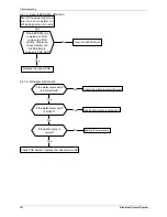
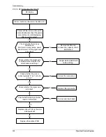
Page 224: ...Troubleshooting 214 Electrical Control System 2 4 2 10 P0 malfunction...
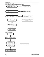
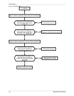
Page 225: ...Troubleshooting Electrical Control System 215 2 4 2 11 P1 malfunction Only for 30K 60K...
Page 226: ...Troubleshooting 216 Electrical Control System 2 4 2 12 P2 malfunction Only for 30K 60K...
Page 227: ...Troubleshooting Electrical Control System 217 2 4 2 13 P3 malfunction...

