background image

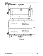
Dimensions 


3rd Generation Ceiling & Floor Type 

97 

2. Dimensions  


Capacity (Btu/h) 

A B C D E 

36K 1285 

675 

235 

1200 

220 

48K, 60K 

1650 

675 

235 

1565 

220 

Summary of Contents for mcd-24hrdn1

Page 1: ...DC INVERTER SERIES Service Manual 2013 LIS B 1306...

Page 2: ......

Page 3: ...formation 1 Part 2 Indoor Units 8 Part 3 Outdoor Units 116 Part 4 Installation 133 Part 5 Electrical Control System 177 The specifications designs and information in this book are subject to change wi...

Page 4: ......

Page 5: ...General Information General Information 1 Part 1 General Information 1 Model Lists 2 2 External Appearance 4 2 1 Indoor Units 4 2 2 Outdoor Units 5 3 Nomenclature 6 4 Features 7...

Page 6: ...roll DC Inverter GMCC MCA2 18HRDN1 Q MCD 18HRDN1 Q MFA 18HRDN1 Q MUB 18HRDN1 Q MTB 18HWDN1 Q MOU 24HDN1 Q Rotary DC Inverter GMCC MCC 24HRDN1 Q MCD 24HRDN1 Q MUB 24HRDN1 Q MTB 24HWDN1 Q MFGA 24ARDN1 Q...

Page 7: ...HRDN1 Q MTB 48HWDN1 Q MHD 48HRDN1 Q MFGA 48ARDN1 R MOU 60HDN1 R Rotary DC Inverter GUANGZHOU MITSUBISHI MCC 60HRDN1 R MCD 60HRDN1 Q MUB 60HRDN1 R MUE 60HRDN1 Q MTB 60HWDN1 R MHD 60HRDN1 R MFGA 60ARDN1...

Page 8: ...al Information 2 External Appearance 2 1 Indoor Units Duct Ceiling Floor Four way Cassette Compact Four way cassette Super slim Four way Cassette GA Floor Standing Console High static pressure duct 3r...

Page 9: ...External Appearance General Information 5 2 2 Outdoor Units Single fan outdoor unit Double fan outdoor unit Double fan outdoor unit...

Page 10: ...tion Designed Time A Time A Designed B Time B Designed C Time C Designed D Time D Designed Product Category C Cassette Type V AHU Type T Duct Type F Console Type U Ceiling Floor Type H High Static Pre...

Page 11: ...r more choice for you 4 4 Low ambient kit is standard for outdoor units except 12K 4 5 Network control function is standard for the indoor units except 12K 4 6 Standard auto restart function and follo...

Page 12: ...Units New Four way Cassette Type Compact 9 Four way Cassette Type 19 Super Slim Cassette Type 27 Duct Type 41 Ceiling Floor Type 57 Console Type 71 High Static Pressure Duct 85 3rd Generation Ceiling...

Page 13: ...ur way Cassette Type Compact 1 Features 10 2 Dimensions 11 3 Service Space 12 4 Wiring Diagrams 13 5 Air Velocity and Temperature Distributions Reference Data 14 6 Electric Characteristics 15 7 Sound...

Page 14: ...7mm The hooks are designed in the four corners of the body which can save installation space 1 3 Electric control box built in design The E box is simply and safely built inside the indoor unit It s c...

Page 15: ...Dimensions 11 2 Dimensions...

Page 16: ...Service Space 12 3 Service Space...

Page 17: ...Wiring Diagrams 13 4 Wiring Diagrams MCA2 12HRDN1 Q MCA2 18HRDN1 Q...

Page 18: ...Air Velocity and Temperature Distributions Reference Data 14 5 Air Velocity and Temperature Distributions Reference Data Airflowvelocity Temperature...

Page 19: ...ndoor Units Power Supply Hz Voltage Min Max MFA MCA2 12HRDN1 Q 50 220 240V 198V 254V 20 MCA2 18HRDN1 Q 50 220 240V 198V 254V 15 Notes MFA Max Fuse Amps A 7 Sound Levels 1 4m Microphone Model Noise lev...

Page 20: ...ST2 9 10 C H 2 11 Alkaline dry batteries AM4 2 Others 12 Owner s manual 1 13 Installation manual 1 9 The Specification of Power Model 12000Btu h 18000 Btu h INDOOR UNIT POWER Phase 1 phase 1 phase Fre...

Page 21: ...Field Wiring 17 10 Field Wiring MCA2 12HRDN1 Q MCA2 18HRDN1 Q...

Page 22: ...Field Wiring 18 MCA2 12HRDN1 Q MCA2 18HRDN1 Q...

Page 23: ...ssette Type 1 Features 22 2 Dimensions 25 3 Service Space 26 4 Wiring Diagrams 27 5 Air Velocity and Temperature Distributions Reference Data 22 6 Electric Characteristics 23 7 Sound Levels 23 8 Acces...

Page 24: ...el with 360 airflow supply Air intake grille lift function for supper thin cassette convenient for maintenance 1 2 3D screw fan technology 3D screw indoor fan technology reduces the air resistance inc...

Page 25: ...ion Fresh air fulfills air quality more healthy and comfortable 1 4 Air passage function Reserves the space for air outlet from the side of indoor unit It s availed to connect air duct from side to ne...

Page 26: ...pumping head is 750mm upmost It s convenient to install drainage piping under most space condition 1 6 LED display Digital LED interface makes the unit more elegant Normally display the setting tempe...

Page 27: ...Dimensions Four way Cassette Type 25 2 Dimensions Unit mm MODEL Btu h A B C H 24000 230 15 9 9 5 260 30000 300 15 9 9 5 330 36000 300 15 9 9 5 330 48000 300 15 9 9 5 330 60000 300 15 9 9 5 330...

Page 28: ...Service Space 26 Four way Cassette Type 3 Service Space 1000mm 1000mm 1000mm 1000m m...

Page 29: ...Wiring Diagrams Four way Cassette Type 27 4 Wiring Diagrams MCC 24HRDN1 Q MCC 30HRDN1 Q...

Page 30: ......

Page 31: ...Wiring Diagrams Four way Cassette Type 21 MCC 36HRDN1 Q MCC 48HRDN1 Q MCC 60HRDN1 R...

Page 32: ...ocity Electronic expansionvalve Oil separator Compressor Lowpressure switch Oil return Capillary Highpressureswitch Lowpressureliquid accumulator Evaporator Capillary Outdoor unit Indoorunit 4 wayvalv...

Page 33: ...98 254 15 MCC 30HRDN1 Q 50 220 240 198 254 15 MCC 36HRDN1 Q 50 220 240 198 254 15 MCC 48HRDN1 Q 50 220 240 198 254 15 MCC 60HRDN1 R 50 220 240 198 254 15 Notes MFA Max Fuse Amps A 7 Sound Levels 1 4m...

Page 34: ...tings Out let pipe sheath 1 Out let pipe clasp 1 Drain joint 1 Seal ring 1 Remote controller Its Frame Remote controller Its Frame 1 Remote controller holder 1 Mounting screw ST2 9 10 C H 2 Alkaline d...

Page 35: ...40V 50Hz 220 240V 50Hz 220 240V 50Hz POWER WIRING mm 2 3 1 0 3 1 0 3 1 0 CIRCUIT BREAKER A 15 15 15 OUTDOOR UNIT POWER Phase 1 phase 1 phase 3 phase Frequency and Voltage 220 240V 50Hz 220 240V 50Hz 3...

Page 36: ...Field Wiring 26 Four way Cassette Type 10 Field Wiring Wiring chart...

Page 37: ...Cassette Type 1 Features 28 2 Dimensions 32 3 Service Space 33 4 Wiring Diagrams 34 5 Air Velocity and Temperature Distributions Reference Data 35 6 Electric Characteristics 36 7 Sound Levels 37 8 Ac...

Page 38: ...to lifting panel design more convenient to clean and maintain the filter optional Old Cassette New slim cassette Volume change Dimension 18K 24K 840 230 840 18K 24K 840 205 840 11 30K 840 300 840 30K...

Page 39: ...be switched on or off by remote controller When pressing the Clean Air button on the remote controller Ionizer will work and the indicator light on display board will shine New air intake I Io on ni...

Page 40: ...n Reserve external air duct more flexible for the air supply 1 5 Built in draining pump Due to the improvement of structure more convenient to repair or replace the draining pump Built in draining pum...

Page 41: ...n wired controller is optional with error code indication function Better man machine conversation interface Undated structure design 4 way wire layout design no raised part at backside more convenien...

Page 42: ...Dimensions 32 Super Slim Cassette Type 2 Dimensions Model A H 18 30 205 235 36 48 245 275 60 287 312...

Page 43: ...Service Space Super Slim Cassette Type 33 3 Service Space 1000mm 1000mm 1000mm 1000m m...

Page 44: ...Wiring Diagrams 34 Super Slim Cassette Type 4 Wiring Diagrams MCD 18HRDN1 Q MCD 24HRDN1 Q MCD 30HRDN1 Q MCD 36HRDN1 Q MCD 48HRDN1 Q MCD 60HRDN1 Q...

Page 45: ...locity Electronic expansionvalve Oil separator Compressor Lowpressure switch Oil return Capillary Highpressureswitch Lowpressureliquid accumulator Evaporator Capillary Outdoor unit Indoorunit 4 wayval...

Page 46: ...door Unit Power Supply Hz Voltage Min Max MFA MCD 18HRDN1 Q 50 220 240 198 254 15 MCD 24HRDN1 Q 50 220 240 198 254 15 MCD 30HRDN1 Q 50 220 240 198 254 15 MCD 36HRDN1 Q 50 220 240 198 254 15 MCD 48HRDN...

Page 47: ...Slim Cassette Type 37 7 Sound Levels 1 4m Microphone Model Noise level dB A H M L MCD 18HRDN1 Q 37 34 32 MCD 24HRDN1 Q 43 41 38 MCD 30HRDN1 Q 46 45 43 MCD 36HRDN1 Q 48 46 45 MCD 48HRDN1 Q 48 46 45 MCD...

Page 48: ...ut let pipe sheath 1 Out let pipe clasp 1 Remote controller Its Frame Remote controller Its Frame 1 Remote controller holder 1 Mounting screw ST2 9 10 C H 2 Remote controller manual 1 Alkaline dry bat...

Page 49: ...ncy and Voltage 220 240V 50Hz 220 240V 50Hz POWER WIRING mm 2 3 1 0 3 1 0 CIRCUIT BREAKER A 15 15 OUTDOOR UNIT POWER Phase 1 phase 1 phase Frequency and Voltage 220 240V 50H 220 240V 50H POWER WIRING...

Page 50: ...Field Wiring 40 Super Slim Cassette Type 10 Field Wiring MCD 18HRDN1 Q MCD 24HRDN1 Q MCD 30HRDN1 Q MCD 36HRDN1 Q MCD 48HRDN1 Q MCD 60HRDN1 Q...

Page 51: ...41 Duct Type 1 Features 42 2 Dimensions 45 3 Service Space 46 4 Wiring Diagrams 47 5 Static Pressure 49 6 Electric Characteristics 51 7 Sound Levels 52 8 Accessories 53 9 The Specification of Power 54...

Page 52: ...ear to the bottom in order to matching the installation condition 1 3 Fresh air intake function Optional for 18 60k Install one duct from the reserved fresh air intake to outdoor Continually inhale th...

Page 53: ...te on off and central control ports Reserved remote on off ports and central control ports can connect the cable of an on off controller or a central controller to realize remote on off control functi...

Page 54: ...0m The unit will realized remoter control The wired controller and the display board can display the error code or production code when the chips detect some failure 1 8 Twins Combination 18k 30k The...

Page 55: ...e Size of outline dimension mounted plug A B C D E F G H I J K L M 12 700 210 635 570 65 493 35 119 595 200 80 740 350 18 920 210 635 570 65 713 35 119 815 200 80 960 350 24 920 270 635 570 65 713 35...

Page 56: ...Service Space 46 Duct Type 3 Service Space Ensure enough space required for installation and maintenance All the indoor units reserve the hole to joint the fresh air pipe The hole size as following...

Page 57: ...Wiring Diagrams Duct Type 47 4 Wiring Diagrams MTB1 12HWDN1 Q MTB 18HWDN1 Q MTB 24HWDN1 Q MTB 30HWDN1 Q...

Page 58: ...Wiring Diagrams 48 Duct Type MTB 36HWDN1 Q MTB 48HWDN1 Q MTB 60HWDN1 R...

Page 59: ...30 40 50 60 70 80 90 Pa 600 700 800 900 1000 1100 Air volume m h 3 External static pressure Pa Highspeed Midspeed 1200 24 000Btu h 36 000Btu h Super high speed 1400 1300 Low speed 10 20 30 40 50 60 70...

Page 60: ...speed High speed External static pressure Pa 3 Air volume m h 1000 90 80 70 60 50 40 30 20 10 Low speed 1600 1900 2800 3100 120 110 Super high speed 3400 100 3100 2800 1900 1600 Low speed 10 20 30 40...

Page 61: ...Voltage Min Max MFA MTB1 12HWDN1 Q 50 220 240 198 254 15 MTB 18HWDN1 Q 50 220 240 198 254 15 MTB 24HWDN1 Q 50 220 240 198 254 15 MTB 30HWDN1 Q 50 220 240 198 254 15 MTB 36HWDN1 Q 50 220 240 198 254 15...

Page 62: ...Discharge Microphone 1 4m Concealed Duct Type Duct Duct Model Noise level dB A H M L MTB1 12HWDN1 Q 37 30 26 MTB 18HWDN1 Q 44 36 33 MTB 24HWDN1 Q 45 43 41 MTB 30HWDN1 Q 46 44 42 MTB 36HWDN1 Q 46 44 4...

Page 63: ...tion sheath 2 Binding tape 1 Seal sponge 1 Drainpipe Fittings for cooling heating Drain joint 1 Seal ring 1 Wired controller Its Frame Wired controller 1 Others Owner s manual 1 Installation manual 1...

Page 64: ...220 240V 50Hz 220 240V 50Hz 220 240V 50Hz POWER WIRING mm 2 3 1 5 3 1 0 3 1 0 3 1 0 CIRCUIT BREAKER A 15 15 15 15 OUTDOOR UNIT POWER Phase 1 phase 1 phase 3 phase Frequency and Voltage 220 240V 50Hz 2...

Page 65: ...Field Wiring Duct Type 55 10 Field Wiring...

Page 66: ...Field Wiring 56 Duct Type Air conditioner link circuit For model 12 For model 18 60...

Page 67: ...Type 1 Features 58 2 Dimensions 60 3 Service Space 61 4 Wiring Diagrams 61 5 Air Velocity and Temperature Distributions Reference Data 64 6 Electric Characteristics 66 7 Sound Levels 66 8 Accessories...

Page 68: ...of warm air 1 2 Brief design Brief design that is suitable for any interior will not only give you cooling and heating performance but also upgrade your lifestyle 1 3 3D airflow Vertical air flow and...

Page 69: ...Panel A Panel B Panel LED display C Panel LED display D Panel 1 6 Convenience operating and easy maintenance Remote controller as standard wired controller for optional The filter without screw fixed...

Page 70: ...ing installation F 20mm G Capacity Btu h A B C D E F G 12000 24000 990 660 203 505 506 907 200 36000 1280 660 203 795 506 1195 200 48000 60000 1670 680 240 1070 450 1542 200 Notes The dimension of 120...

Page 71: ...Service Space Ceiling Floor Type 61 3 Service Space C 35mm 35mm 35mm 1000mm 4 Wiring Diagrams MUB 12HRDN1 Q...

Page 72: ...Wiring Diagrams 62 Ceiling Floor Type MUB 18HRDN1 Q MUB 24HRDN1 Q MUB 30HRDN1 Q...

Page 73: ...tion SW2 Floor or Ceiling installation selection SW3 Temperature compensation selection The default temperature compensation value is 1 for floor installation and 6 for ceiling installation and can no...

Page 74: ...ow velocity Electronic expansion valve Oil separator Compressor Low pressure switch Oil return Capillary High pressure switch Low pressure liquid accumulator Evaporator Capillary Outdoor unit Indoor u...

Page 75: ...Air Velocity and Temperature Distributions Reference Data Ceiling Floor Type 65 Discharge angle 60 FLOOR Airflow velocity Temperature...

Page 76: ...B 30HRDN1 Q 50 220 240 198 254 15 MUB 36HRDN1 Q 50 220 240 198 254 15 MUB 48HRDN1 Q 50 220 240 198 254 15 MUB 60HRDN1 R 50 220 240 198 254 15 Notes MFA Max Fuse Amps A 7 Sound Levels Microphone 1m 1m...

Page 77: ...s Name Shape Quantity 1 Hook 2 2 Hanging arm 2 Remote controller Its holder 3 Remote controller 1 4 Remote controller holder 1 5 Mounting screw ST2 9 10 C H 2 6 Alkaline dry batteries AM4 2 Others 7 O...

Page 78: ...50Hz 220 240V 50Hz 220 240V 50Hz 220 240V 50Hz POWER WIRING mm 2 3 1 5 3 1 0 3 1 0 3 1 0 CIRCUIT BREAKER A 20 15 15 15 OUTDOOR UNIT POWER Phase 1 phase 1 phase 3 phase Frequency and Voltage 220 240V 5...

Page 79: ...Field Wiring Ceiling Floor Type 69 10 Field Wiring...

Page 80: ...Field Wiring 70 Ceiling Floor Type For model 12 For model 18 60...

Page 81: ...eatures 73 2 Dimensions 76 3 Service Space 77 4 Wiring Diagrams 78 5 Air Velocity and Temperature Distributions Reference Data 79 6 Electric Characteristics 80 7 Sound Levels 81 8 Accessories 82 9 The...

Page 82: ......

Page 83: ...ed on or room temp is still high cold air will be blown out from top and bottom air outlet to cool down the room quickly Air outlet from top to maintain room temp When the room has been cooled down or...

Page 84: ...eds Low noise and energy saving Advanced centrifugal fan technology makes a fast airflow and reduces the indoor noise lower to 28dB 1 6 Golden fin is optional 1 7 Active carbon filter is standard 1 8...

Page 85: ...Features Console Type 75...

Page 86: ...Dimensions 76 Console Type 2 Dimensions MFA 12HRDN1 Q MFA 18HRDN1 Q...

Page 87: ...Service Space Console Type 77 3 Service Space...

Page 88: ...Wiring Diagrams 78 Console Type 4 Wiring Diagrams MFA 12HRDN1 Q MFA 18HRDN1 Q...

Page 89: ...Air Velocity and Temperature Distributions Reference Data Console Type 79 5 Air Velocity and Temperature Distributions Reference Data Discharge angle 60 Airflow velocity Temperature...

Page 90: ...acteristics 80 Console Type 6 Electric Characteristics Model Indoor Unit Power Supply Hz Voltage Min Max MFA MFA 12HRDN1 Q 50 220 240V 198V 254V 16 MFA 18HRDN1 Q 50 220 240V 198V 254V 16 Notes MFA Max...

Page 91: ...Sound Levels Console Type 81 7 Sound Levels 1 5m 1m Microphone Model Noise level dB A Highest Higher H M L MFA 12HRDN1 Q 38 35 33 31 28 MFA 18HRDN1 Q 44 41 39 37 34...

Page 92: ...2 Others Installation manual 1 Owner s manual 1 9 The Specification of Power Model 12000Btu h 18000 Power Phase 1 phase 1 phase Frequency and Voltage 220 240V 50Hz 220 240V 50Hz Circuit breaker A 20...

Page 93: ...Field Wiring Console Type 83 10 Field Wiring...

Page 94: ...Field Wiring 84 Console Type...

Page 95: ...re Duct 85 High Static Pressure Duct 1 Features 86 2 Dimensions 87 3 Service Space 88 4 Wiring Diagrams 89 5 Fan Performances 90 6 Electric Characteristics 91 7 Sound Levels 91 8 Accessories 92 9 The...

Page 96: ...oms like large stores and factories 1 2 Easy maintenance Reduce time and cost easily removable fan motor design 1 Control box 2 Fan casing 3 Motor assembly 4 Bottom panel 1 3 Flexible Installation Dif...

Page 97: ...Dimensions High Static Pressure Duct 87 2 Dimensions MHD 36HRDN1 Q MHD 48HRDN1 Q MHD 60HRDN1 R...

Page 98: ...ervice Space 88 High Static Pressure Duct 3 Service Space Ensure enough space required for installation and maintenance 500mm or more 600mm or more Indoor unit 600mmx600mm Maintenance and repair space...

Page 99: ...Wiring Diagrams High Static Pressure Duct 89 4 Wiring Diagrams MHD 36HRDN1 Q MHD 48HRDN1 Q MHD 60HRDN1 R...

Page 100: ...Fan Performances 90 High Static Pressure Duct 5 Fan Performances MHD 36HRDN1 Q MHD 48HRDN1 Q MHD 60HRDN1 R...

Page 101: ...Min Max MFA MHD 36HRDN1 Q 50 220 240V 198V 254V MHD 48HRDN1 Q 50 220 240V 198V 254V MHD 60HRDN1 R 50 220 240V 198V 254V Note MFA Max Fuse Amps A 7 Sound Levels Duct Duct Microphone 1 4m Suction Disch...

Page 102: ...h 2 2 Binding tape 1 Drainpipe Fittings 3 Drain joint 1 4 Seal ring 1 Wireless Remote controller Its Frame 5 Wireless Remote controller 1 6 Frame 1 7 Mounting screw ST2 9 10 C H 2 8 Alkaline dry batte...

Page 103: ...ncy and Voltage 220 240V 50Hz 220 240V 50Hz POWER WIRING mm2 3 1 0 3 1 0 CIRCUIT BREAKER A 15 15 OUTDOOR UNIT POWER Phase 1 phase 3 phase Frequency and Voltage 220 240V 50Hz 380 420V 50Hz POWER WIRING...

Page 104: ...Field Wiring 94 High Static Pressure Duct 10 Field Wiring...

Page 105: ...n Ceiling Floor Type 95 3rd Generation Ceiling Floor Type 1 Features 96 2 Dimensions 97 3 Service Space 98 4 Wiring Diagrams 99 5 Electric Characteristics 100 6 Sound Levels 101 7 Accessories 102 8 Th...

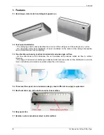
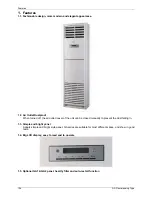
Page 106: ...lighting 1 3 Two direction auto swing vertical horizontal and wide angle air flow Air flow directional control minimizes the air resistance and produces wilder air flow to vertical direction The range...

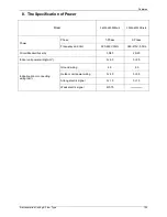
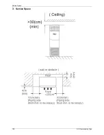
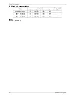
Page 107: ...Dimensions 3rd Generation Ceiling Floor Type 97 2 Dimensions Capacity Btu h A B C D E 36K 1285 675 235 1200 220 48K 60K 1650 675 235 1565 220...

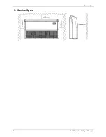
Page 108: ...Service Space 98 3rd Generation Ceiling Floor Type 3 Service Space...

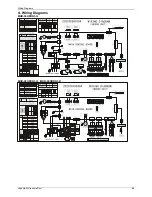
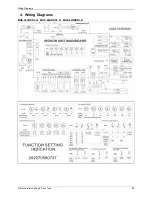
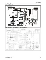
Page 109: ...Wiring Diagrams 3rd Generation Ceiling Floor Type 99 4 Wiring Diagrams MUE 36HRDN1 Q MUE 48HRDN1 Q MUE 60HRDN1 R...

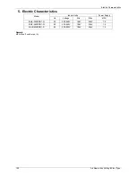
Page 110: ...Ceiling Floor Type 5 Electric Characteristics Model Indoor Units Power Supply Hz Voltage Min Max MFA MUE 36HRDN1 Q 50 220 240V 198V 254V 15 MUE 48HRDN1 Q 50 220 240V 198V 254V 15 MUE 60HRDN1 R 50 220...

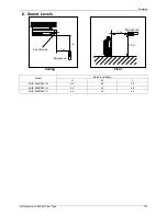
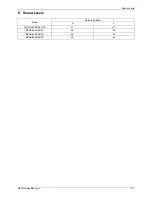
Page 111: ...Generation Ceiling Floor Type 101 6 Sound Levels Microphone 1m 1m Air outlet side 1 5m 1m Microphone Ceiling Floor Model Noise level dB A H M L MUE 36HRDN1 Q 53 49 45 MUE 48HRDN1 Q 54 52 48 MUE 60HRDN...

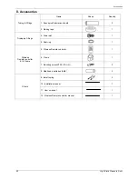
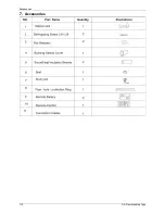
Page 112: ...r Type 7 Accessories Remote controller Its holder 1 Remote controller 1 2 Remote controller holder 1 3 Mounting screw ST2 9 10 C H 2 4 Alkaline dry batteries AM4 2 Others 5 Owner s manual 1 6 Installa...

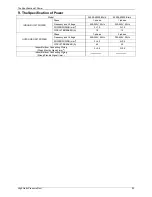
Page 113: ...u h Power Phase 1 Phase 3 Phase Frequency and Volt 220 240V 50Hz 380 415V 50Hz Circuit Breaker Fuse A 50 30 25 20 Indoor unit power wiring mm 3 4 0 5 2 5 Indoor out door connecting wiring mm Ground wi...

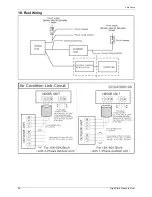
Page 114: ...Field Wiring 104 3rd Generation Ceiling Floor Type 9 Field Wiring MUE 48HRDN1 Q MUE 60HRDN1 R...

Page 115: ...Type 105 GA Floor standing Type 1 Features 106 2 Dimensions 107 3 Service Space 108 4 Wiring Diagrams 109 5 Electric Characteristics 110 6 Sound Levels 111 7 Accessories 112 8 The Specification of Po...

Page 116: ...ff the air outlet louver of the unit can be closed manually to prevent the dust falling in 1 3 Simple and bright panel Adopts simple and bright style panel GA series are suitable for most different sp...

Page 117: ...Dimensions GA Floor standing Type 107 2 Dimensions Dimension Mode W mm D mm H mm MFGA 24ARDN1 QC2 510 240 1695 MFGA 36ARDN1 R 550 350 1800 MFGA 48ARDN1 R 610 390 1925 MFGA 60ARDN1 R 610 390 1925...

Page 118: ...Service Space 108 GA Floor standing Type 3 Service Space...

Page 119: ...Wiring Diagrams GA Floor standing Type 109 4 Wiring Diagrams MFGA 24ARDN1 QC2 MFGA 36ARDN1 R MFGA 48ARDN1 R MFGA 60ARDN1 R...

Page 120: ...c Characteristics Model Indoor Units Power Supply Hz Voltage Min Max MFA MFGA 24ARDN1 QC2 50 220 240V 198V 254V 15 MFGA 36ARDN1 R 50 220 240V 198V 254V 15 MFGA 48ARDN1 R 50 220 240V 198V 254V 15 MFGA...

Page 121: ...Sound Levels GA Floor standing Type 111 6 Sound Levels Model Noise level dB A H L MFGA 24ARDN1 QC2 51 47 MFGA 36ARDN1 R 56 52 MFGA 48ARDN1 R 59 55 MFGA 60ARDN1 R 59 56...

Page 122: ...Accessories 112 GA Floor standing Type 7 Accessories...

Page 123: ...cy and Voltage 220 240V 50Hz 220 240V 50Hz POWER WIRING mm2 3 1 0 5 1 3 CIRCUIT BREAKER A 15 15 OUTDOOR UNIT POWER Phase 1 phase 3 phase Frequency and Voltage 220 240V 50Hz 380 420V 50Hz POWER WIRING...

Page 124: ...Field Wiring 114 GA Floor standing Type 9 Field Wiring MFGA 24ARDN1 QC2...

Page 125: ...Field Wiring GA Floor standing Type 115 MFGA 36ARDN1 R MFGA 48ARDN1 R MFGA 60ARDN1 R...

Page 126: ...door Units 116 Outdoor Units Part 3 Outdoor Units 1 Dimensions 117 2 Service Space 120 3 Piping Diagrams 121 4 Wiring Diagrams 123 5 Electric Characteristics 130 6 Operation Limits 131 7 Sound Levels...

Page 127: ...del Unit mm A B C D E F H MOU 12HDN1 Q 760 530 290 315 270 285 590 MOU 18HDN1 Q 760 530 290 315 270 285 590 MOU 24HDN1 Q 845 560 335 360 312 320 700 MOU 30HDN1 Q 900 590 333 355 302 315 860 MOU 36HDN1...

Page 128: ...Dimensions 118 Outdoor Units Model Unit mm A B C D E F H MOU 48HDN1 Q 940 600 376 400 340 360 1245 MOU 48HDN1 R MOU 60HDN1 R...

Page 129: ...Dimensions Outdoor Units 119 New MOU 48HDN1 Q MOU 48HDN1 R MOU 60HDN1 R...

Page 130: ...Service Space 120 Outdoor Units 2 Service Space More than 60cm More than 30cm More than 60cm More than 200cm Air inlet Air inlet More than 30cm Air outlet Wall or obstacle Maintain channel...

Page 131: ...sor Accumulator T5 Discharge temp sensor T4 Ambient temp sensor INDOOR OUTDOOR For MOU 24HDN1 Q the accumulator is not included MOU 18HDN1 Q MOU 24HDN1 Q 220075301400 LIQUID SIDE GAS SIDE HEAT EXCHANG...

Page 132: ...valve CAPILIARY TUBE Accumulator MOU 36HDN1 Q MOU 36HDN1 R MOU 48HDN1 Q MOU 48HDN1 R MOU 60HDN1 R LIQUID SIDE GAS SIDE HEAT EXCHANGE EVAPORATOR HEAT EXCHANGE CONDENSER Compressor 2 WAY VALVE 3 WAY VA...

Page 133: ...Wiring Diagrams Outdoor Units 123 4 Wiring Diagrams MOU 12HDN1 Q MOU 18HDN1 Q...

Page 134: ...Wiring Diagrams 124 Outdoor Units MOU 24HDN1 Q 220075301400 MOU 24HDN1 Q 220075302030...

Page 135: ...Wiring Diagrams Outdoor Units 125 MOU 30HDN1 Q MOU 36HDN1 Q 220075501600...

Page 136: ...Wiring Diagrams 126 Outdoor Units MOU 36HDN1 Q 220075501990...

Page 137: ...Wiring Diagrams Outdoor Units 127 MOU 48HDN1 Q MOU 48HDN1 Q New Body...

Page 138: ...Wiring Diagrams 128 Outdoor Units MOU 36HDN1 R MOU 48HDN1 R MOU 60HDN1 R...

Page 139: ...Wiring Diagrams Outdoor Units 129 MOU 48HDN1 R MOU 60HDN1 R New Body...

Page 140: ...e Min Max MOU 12HDN1 Q 50 220 240 198 254 MOU 18HDN1 Q 50 220 240 198 254 MOU 24HDN1 Q 50 220 240 198 254 MOU 30HDN1 Q 50 220 240 198 254 MOU 36HDN1 Q 50 220 240 198 254 MOU 36HDN1 R 50 380 415 342 44...

Page 141: ...above conditions certain safety protection features may come into operation and cause the unit to operate abnormally 2 The room relative humidity should be less than 80 If the air conditioner operate...

Page 142: ...l Noise level dB A H MOU 12HDN1 Q 48 MOU 18HDN1 Q 51 MOU 24HDN1 Q 220075301400 54 MOU 24HDN1 Q 220075301401 59 MOU 24HDN1 Q 220075302030 55 MOU 30HDN1 Q 55 MOU 36HDN1 Q 55 MOU 36HDN1 R 63 MOU 48HDN1 Q...

Page 143: ...unit installation 136 4 Outdoor unit installation Side Discharge Unit 163 5 Refrigerant pipe installation 165 6 Drainage pipe installation 168 7 Vacuum Drying and Leakage Checking 172 8 Additional ref...

Page 144: ...Wiring connection and electric safety checking Test operation Refrigerant pipe installation and insulation Drainage pipe installation and insulation Indoor unit installation location selection Outdoor...

Page 145: ...on The place shall easily support the outdoor unit s weight Locate the outdoor unit as close to indoor unit as possible The piping length and height drop can not exceed the allowable value The place w...

Page 146: ...ion 3 1 1 Service space for indoor unit 3 1 2 Bolt pitch 3 1 3 Install the pendant bolt Select the position of installation hooks according to the hook holes positions showed in upper picture Drill fo...

Page 147: ...the 4 suspender through the 4 hanger of the main body to suspend it Adjust the hexangular nuts on the four installation hooks evenly to ensure the balance of the body Use a leveling instrument to make...

Page 148: ...ation 138 Installation 3 1 5 Install the panel Remove the grille Hang the panel to the hooks on the mainbody Tighten the screws under the panel hooks till the panel closely stick on the ceiling to avo...

Page 149: ...139 Hang the air in grill to the panel then connect the lead terminator of the swing motor and that of the control box with corresponding terminators on the body respectively Note The panel shall be...

Page 150: ...Model A H Remark 18 230 260 R410A and R22 Cooling Cooling Heating 24 230 260 R410A and R22 Cooling Cooling Heating 30 60 300 330 R410A and R22 Cooling Cooling Heating 3 2 2 Bolt pitch 3 2 3 Install t...

Page 151: ...uts on the four installation hooks evenly to ensure the balance of the body Use a leveling instrument to make sure the levelness of the main body is within 1 Adjust the position to ensure the gaps bet...

Page 152: ...Indoor unit installation 142 Installation 3 2 5 Install the panel Remove the grille Remove the 4 corner covers Hang the panel to the hooks on the mainbody...

Page 153: ...ck on the ceiling to avoid condensate water Hang the air in grill to the panel then connect the lead terminator of the swing motor and that of the control box with corresponding terminators on the bod...

Page 154: ...outline dimension mounted plug L M 12 740 350 18 960 350 24 960 350 30 36 1180 490 48 60 1240 500 3 3 3 Install the pendant bolt Select the position of installation hooks according to the hook holes...

Page 155: ...hexangular nuts on the four installation hooks evenly to ensure the balance of the body Use a leveling instrument to make sure the levelness of the main body is within 1 3 3 5 Install the air filter...

Page 156: ...hed seal sponge as per the indicating place in the following fig and then change the mounting positions of air return panel and air return flange When install the filter mesh please plug it into flang...

Page 157: ...nstallation Installation 147 3 4 HESP duct indoor unit installation 3 4 1 Service space for indoor unit 500mm or more 600mm or more Indoor unit 600mmx600mm Maintenance and repair space 3 4 2 Bolt pitc...

Page 158: ...positions on the ceiling Then embed the expansible hooks fittings 3 4 4 Install the main body Make the 4 suspender through the 4 hanger of the main body to suspend it Adjust the hexangular nuts on the...

Page 159: ...Indoor unit installation Installation 149 3 5 Ceiling floor indoor unit installation 3 5 1 Service space for indoor unit 3 5 2 Bolt pitch Ceiling installation Floor standing installation...

Page 160: ...e ceiling Then embed the expansible hooks fittings Floor standing installation Fix the hook with tapping screw onto the wall Refer to picture below 3 5 4 Install the main body Ceiling installation The...

Page 161: ...sides some of the models 60 do not do this For some of the models 60 please securely tighten the mounting bolts on both sides Then install the side panels and grilles back to the main unit Floor stand...

Page 162: ...door unit installation 3 6 1 Service space for indoor unit 3 6 2 Install the main body Fix the hook with tapping screw onto the wall Hang the indoor unit on the hook The bottom of body can touch with...

Page 163: ...ing Heating 36 48 245 275 R410A and R22 Cooling Cooling Heating 60 287 317 R410A and R22 Cooling Cooling Heating 3 7 2 Bolt pitch 3 7 3 Install the pendant bolt Select the position of installation hoo...

Page 164: ...leveling instrument to make sure the levelness of the main body is within 1 Adjust the position to ensure the gaps between the body and the four sides of ceiling are even The body s lower part should...

Page 165: ...g the panel to the hooks on the mainbody If the panel is with auto lift grille please watch the ropes lifing the grille DO NOT make the ropes enwinded or blocked Tighten the screws under the panel hoo...

Page 166: ...r in grill to the panel then connect the lead terminator of the swing motor and that of the control box with corresponding terminators on the body respectively Install the 4 corner covers back Note Th...

Page 167: ...ease reserve space for installation and maintenance 3 8 1 2 Please check the elevation difference between the indoor unit and the outdoor unit the length of the refrigerant pipe and the curved places...

Page 168: ...ront panel before connecting the pipes wires Pull down the two knobs on the grille take off the two screws then the air inlet grille goes free 3 8 2 3 Take the Pipe Clip off before connecting the pipe...

Page 169: ...Installation 159 3 9 3rd generation ceiling floor indoor unit installation 3 9 1 Service space for indoor unit 3 9 2 Bolt pitch Ceiling installation Capacity Btu h D E 36K 1200 220 48K 60K 1565 220 W...

Page 170: ...owed in upper picture Drill four holes of 12mm 45 50mm deep at the selected positions on the ceiling Then embed the expansible hooks fittings Wall mounted installation Install the tapping screws onto...

Page 171: ...Indoor unit installation Installation 161 Locate the hanging arm on the hanging screw bolt Prepare the mounting bolts on the unit Put the side panels and grilles back...

Page 172: ...n 162 Installation Wall mounted installation Hang the indoor unit by insert the tapping screws into the hanging arms on the main unit The bottom of body can touch with floor or suspended but the body...

Page 173: ...stallation 163 4 Outdoor unit installation Side Discharge Unit 4 1 Service space for outdoor unit 4 2 Bolt pitch Model B C D 24K 590 333 355 30K 624 366 396 36K 624 366 396 48K 600 375 400 60K 600 375...

Page 174: ...g it with a sling Never hold the inlet of the outdoor unit to prevent it from deforming Do not touch the fan with hands or other objects Do not lean it more than 45 and do not lay it sidelong Make con...

Page 175: ...es 5 2 3 Measure the necessary pipe length 5 2 4 Cut the selected pipe with pipe cutter Make the section flat and smooth 9 0 Lean Crude Burr o 5 2 5 Insulate the copper pipe Before test operation the...

Page 176: ...ent pipe connection Pipe Diameter Torque Sketch map kgf cm N cm 1 4 6 35 144 176 1420 1720 3 8 9 52 333 407 3270 3990 1 2 12 7 504 616 4950 6030 5 8 15 9 630 770 6180 7540 3 4 19 990 1210 9270 11860 5...

Page 177: ...on 167 5 3 2 Size of joint pipes for indoor unit R410a 5 3 3 Size of joint pipes for outdoor unit R410a 5 3 4 The branching pipe must be installed horizontally error angle of it should not large than...

Page 178: ...er flowrate is decided by the capacity of indoor unit Relationship between water flowrate and capacity of indoor unit Capacity x1000Btu Water flowrate l h 12 2 4 18 4 24 6 30 7 36 8 42 10 48 12 60 14...

Page 179: ...ng distance Gas bag 6 2 5 The horizontal pipe layout should avoid converse flow or bad flow Drainage pipe Water flow Drainage pipe Drainage pipe Drain tee Drain tee Water flow Water flow Water flow Wa...

Page 180: ...h Refer the following picture for installation reference Flexible pipe 300mm Hanger A A Length of horizontal pipe 150mm B Lift height the pump head of water pump Down incline pipe B 6 2 8 Blowhole set...

Page 181: ...at drainage outlet In light of the length of drainage pipe water shall be discharged about 1 minute delayed 2 3 Stop the operation of air conditioner power off the power supply and put the cover of wa...

Page 182: ...Hg after 1 5 hours of drying check whether there is leakage source 4 Leakage test After the vacuum degree reaches 755mmHg stop vacuum drying and keep the pressure for 1 hour If the indicator of vacuum...

Page 183: ...the liquid pipe m Note Refrigerant may only be charged after performed the vacuum drying process Always use gloves and glasses to protect your hands and eyes during the charge work Use electronic scal...

Page 184: ...environment place the layer of insulation should be thicker accordingly 9 1 4 Installation highlights of insulation construction Gas pipe and liquid pipe shall be insulated separately if the gas pipe...

Page 185: ...eld wiring construction should be finished by qualified electrician Air conditioning equipment should be grounded according to the local electrical regulations Current leakage protection switch should...

Page 186: ...units The gas side and liquid side stop values are both opened The air conditioner is pre heated by turning on the power 11 3 Test operation Set the air conditioner under the mode of COOLING by remote...

Page 187: ...Electrical Control System Electrical Control System 177 Part 5 Electrical Control System 1 Electrical Control Function 178 2 Troubleshooting 194 3 Controller 225...

Page 188: ...requency will be limited as below rules For 12k models Compressor discharge temp T5 115 for 5s compressor stops 108 T5 115 decrease the frequency to the lower level every 3 minutes till F1 90 T5 105 k...

Page 189: ...disabled and no setting temperature is displayed 3 Indoor fan can be set to high med low auto 4 The louver operates same as in cooling mode 5 Auto fan For Compact Cassette 12k GA floor standing For G...

Page 190: ...3 2 1 Outdoor PMW open angle control The unit is working in cooling mode with the EXV open 300P for 3 minutes then adjusting PMW open angle according to the temperature of compressor discharge every 2...

Page 191: ...rules In cooling mode indoor fan runs all the time and the speed can be selected as high medium low and auto The auto fan For Compact cassette12k For GA floor standing For Ceiling and floor 12k Consol...

Page 192: ...ssor frequency will not be limited For other models When T2 2 and lasts for 3 minutes the indoor has no capacity demand and resume till T2 7 1 3 2 5 Condenser high temperature T3 protection For 12k mo...

Page 193: ...ing PMW open angle according to the temperature of compressor discharge every 2 minutes 1 3 3 2 Outdoor fan running rules For 12k models 17 15 Low High For other models 14 12 Low High 1 3 3 3 Indoor f...

Page 194: ...nding T1 TS T 3 2 High Low For Ceiling and floor 12k Console 12k 2 5 T1 Ts T 2 High Low 1 Medium 1 5 For A5 duct 12k 3 T1 Ts T 2 High Low 1 Medium For Console 18k Compact cassette 18k Big Cassette 24k...

Page 195: ...program judges if T2 has decreased more than 5 When T2 has decreased more than 5 enter the defrosting mode No matter what value of the T4 is and whether the T2 drops more than 5 or not if the machine...

Page 196: ...0P PMV PMV running 6 mins with 300P Compressor 10S 30S TimeA 10S no longer than 10min Condition of ending defrosting If any one of following items is satisfied defrosting will stop and the machine wil...

Page 197: ...of the following conditions 1 Compressor is off 2 T3 TempEnterDefrost_ADD Time2 Time conditions Meet the following conditions 1 Running in heating mode 2 T4 3 3 Compressor is on 4 T3 TempEnterDefrost...

Page 198: ...ng frequency decreases to the lower level every 20s When the frequency decreases to F2 and the T2 is still over TEH2 for 3 minutes the compressor will stop T2 48 or TEH2 T2 48 for 6 minutes the freque...

Page 199: ...mperature protection and outdoor unit frequency limit are active and the same as that in cooling mode 1 3 5 4 The outdoor fan operates the same as in cooling mode For other models Drying mode works th...

Page 200: ...n reaching the setting time If the timing is more than 7 hours the machine will not stop until reaches the setting time in sleep mode 1 3 7 6 When user uses timer on function in sleep modes sleep mode...

Page 201: ...ump is on before the unit is off it will delay 2 minutes to be off If there is a water full error the drain pump will be on when the error occurs Afterwards If the error disappears in 2 minutes the dr...

Page 202: ...of voltage 12 Indoor unit running mode code Off 0 Fan only 1 Cooling 2 Heating 3 Forced cooling 4 13 Outdoor unit running mode code 14 EXV open angle Actual data 4 If the value is higher than 99 the d...

Page 203: ...de is higher than 99 the digital display tube will show single digit and tens digit For example the digital display tube show 5 0 it means the capacity demand is 15 the digital display tube show 60 it...

Page 204: ...Compact cassette High static pressure Duct 2 1 3 Icon explanation on indoor display board Ceiling floor 2 1 4 Icon explanation on indoor display board A5 Duct OPERATION TIMER DEF FAN ALARM Temporary b...

Page 205: ...roubleshooting Electrical Control System 195 2 1 5 Icon explanation on indoor display board Console 2 1 6 Display board of auto lifting panel of 4 way cassette 2 1 7 Display board of GA floor standing...

Page 206: ...Troubleshooting 196 Electrical Control System 2 1 8 Icon explanation on indoor display board 3rd generation ceiling floor...

Page 207: ...h at 0 5Hz For ceiling floor 12K NO Malfunction Running lamp Timer lamp Defrosting lamp Alarm lamp 1 Communication malfunction between indoor and outdoor units X X X 2 Open or short circuit of T1 temp...

Page 208: ...er current protection O O 9 Top temperature protection of compressor O X 10 Inverter compressor drive protection X 11 Indoor fan Speed has been out of control O 12 Outdoor fan malfunction X O O light...

Page 209: ...ircuit of T1 temperature sensor X X X E2 3 Open or short circuit of T2 temperature sensor X X X E3 4 Open or short circuit of T2B temperature sensor X X X E4 5 Full water malfunction X X X EE 6 Indoor...

Page 210: ...tion malfunction between main PCB and up down panel PCB X F0 10 Up down panel malfunction X F1 11 Up down panel is not closed X O F2 12 Communication malfunction between master unit and slave unit X X...

Page 211: ...ween IPM board and outdoor main board E4 Open or short circuit of T3 or T4 temperature sensor E5 Voltage protection of compressor E6 PFC module protection Only for 36K 48K with 1 phase P0 Top temperat...

Page 212: ...indoor unit 2 4 1 1 Open or short circuit of temperature sensor Check the connections between temperature sensor and PCB Are the connections good Correct the connections No Yes Yes Replace indoor or o...

Page 213: ...o No Check whether the power is on Replace outdoor main board Yes Whether the outdoor unit is power on Check whether the communication wire between the indoor and outdoor unit is connected correctly Y...

Page 214: ...EPROM well Replace the indoor PCB Shut off the power supply and turn it on 5 seconds later Is it still displaying the error code 2 4 1 4 Full water malfunction If the water level switch is inserted we...

Page 215: ...e wires of fan motor Are all the connections good No Yes No Correct the connections No Yes Replace indoor main PCB Is it still displaying the error code Yes Yes Check the voltage between port 1 and 6...

Page 216: ...er strong current protection Only for 12k 2 4 2 2 E0 malfunction If the EEPROM chip is welded on PCB replace the PCB directly Otherwise check whether the EEPROM chip plugged in PCB well Yes No Yes Ins...

Page 217: ...extinguished Change the indoor main PCB No Change the outdoor main PCB No Check all the wirings between indoor and outdoor indoor PCB and outdoor PCB following the wiring diagram Are all the wirings...

Page 218: ...erference Increase the capacity of anti interference Yes Yes Replace the signal wire Yes Pull out and insert back No No Replace indoor PCB is the error distinguished Yes Replace the outdoor PCB No Che...

Page 219: ...light Check the signal wire between the IPM module and the main board is it connected good Reconnect and retry Is error still display Replace IPM board and then check whether the system can run norma...

Page 220: ...r the resistance of condenser temp sensorT3 is wrong refer to the Appendix 1 Yes Connect the wiring well Yes Judge 2 Outdoor ambient temp sensor T4 is malfunction No Replace outdoor ambient temperatur...

Page 221: ...supply Check whether the voltage of IPM board P and N is normal DC277 356V for 18K 24K 30KBtu h DC277 410V for 36K 48KBtu h Replace bridge rectifiers and then check whether the system can run normally...

Page 222: ...1 L 2 L 3 is about 380VAC Check the power supply Check whether the voltage range of P N on IPM module is normal DC 350 650V Replace bridge rectifiers and then check whether the system can run normall...

Page 223: ...Troubleshooting Electrical Control System 213 2 4 2 9 E6 malfunction Only for 36K 48K with 1 phase...

Page 224: ...Troubleshooting 214 Electrical Control System 2 4 2 10 P0 malfunction...

Page 225: ...Troubleshooting Electrical Control System 215 2 4 2 11 P1 malfunction Only for 30K 60K...

Page 226: ...Troubleshooting 216 Electrical Control System 2 4 2 12 P2 malfunction Only for 30K 60K...

Page 227: ...Troubleshooting Electrical Control System 217 2 4 2 13 P3 malfunction...

Page 228: ...harge temp is more than 115 C Check whether the wiring connection is right between compressor discharge temp sensor and PCB according to wiring diagrams Method Check whether the resistance of compress...

Page 229: ...ge 1 Check whether the outdoor ambient temperature is higher than 50 No Judge 3 The refrigerant pipe is blocked Let the refrigerant out then use the high pressure nitrogen or refrigerant to blow pipe...

Page 230: ...whether the connecting line of the compressor is connected correctly or tightly Replace the IPM module check whether the system can work normally No No Replace the main board check whether the system...

Page 231: ...or not No No No Connect it well check ok or not Check whether the connecting line of the compressor is connected correctly or tightly Replace the IPM module check whether the system can work normally...

Page 232: ...and the indoor fan is running normal No Check refrigerant system such as clogging of capillary etc No Clean the heat exchanger and the air outlet Reconnect and retest No Whether the connection is goo...

Page 233: ...6 13059 76 1 34105 116 0 40060 3 41 5878 37 5 87359 77 1 29078 117 0 38991 2 39 8239 38 5 62961 78 1 25423 118 0 37956 1 37 1988 39 5 39689 79 1 21330 119 0 36954 0 35 2024 40 5 17519 80 1 17393 120 0...

Page 234: ...489 5 234 9 35 35 78 75 8 084 115 2 422 4 222 8 36 34 32 76 7 82 116 2 357 3 211 4 37 32 94 77 7 566 117 2 294 2 200 7 38 31 62 78 7 321 118 2 233 1 190 5 39 30 36 79 7 086 119 2 174 0 180 9 40 29 15...

Page 235: ...ireless Remote Controller 3 1 1RG51Q1 BGE General Function for wireless remote controller Model RG51Q1 BGE Rated voltage 3 0V 2pieces of LR03 7 batteries Min voltage for sending signal of CPU 2 4V Eff...

Page 236: ...air conditioner 8 FAN SPEED Fan speed will be selected in following sequence once pressing this button AUTO LOW MED HIGH 9 TIME ON For time ON setting Once pressing this button the time will increase...

Page 237: ...tting SWING AIR DIRECTION Res et 13 1 Adjust Decrease the set temp Keeping pressing will decrease the temp with 1 per 0 5s 2 Adjust Increase the set temp Keeping pressing will increase the temp with...

Page 238: ...mode only NOTE While the unit is running under Energy saving mode it would be cancelled if press MODE FAN SPEED or ON OFF button 11 TIME OFF For time OFF setting Once pressing this button the time wil...

Page 239: ...s button to change the swing angle of the louver The swing angle of the louver is 6o for each press When the louver swing at a certain angle which would affect the cooling and heating effect of the ai...

Page 240: ...will appear on the remote controller display when the lock function is activated 14 TURBO Push this button to activate cancel the Turbo function which enables the unit to reach the preset temperature...

Page 241: ...seconds then push and button to adjust minute When set clock or alter clock setting must push the confirm button to complete the setting Name and function of LCD on the wire controller 1 Mode select...

Page 242: ...display the set temperature Press the buttons of and to set temperature at the mode of FAN there is no figure display in the area Remark The wired controller will reset to factory setting with auto mo...

Page 243: ...ler Electrical Control System 233 NOTE Never turn screws too tightly or else the cover would be dented or the Liquid Crystal breaks Please leave enough long cable for maintenance of the Wire Controlle...

Reviews: