


4-18
PCWS 2015 Setup Guide - 2nd Edition
Installing and Operating the Workstation 2015
Operation
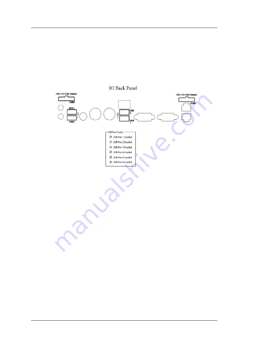
The USB Port Config tab contains six checkboxes, corresponding to a
specific IO Panel connector. This includes the standard Type A ports USB1
through USB4 and the optional powered USB ports, USB5 and USB6. The
location of each connector is shown in the ‘IO Back Panel’ illustration.
All IO Panel USB ports are enabled when the workstation is shipped as
shown in the Figure below.
Figure 4-10: IO Panel USB Port Identification
•
To disable a USB port, touch the box to remove the check mark from the
corresponding port. To enable a USB port touch the box and the
check-mark appears.
•
The change in USB port status take effect immediately, a restart is not
required.
•
When complete, exit the Diagnostics Utility.
•
Using the CMOS jumper or updating the BIOS resets all USB ports to
enabled.
Summary of Contents for PCWS 2015
Page 32: ...1 20 PCWS 2015 Setup Guide 2nd Edition What is the PCWS 2015 Approvals...
Page 68: ...2 36 PCWS 2015 Setup Guide 2nd Edition PCWS 2015 BIOS Exit...
Page 120: ...3 52 PCWS 2015 Setup Guide 2nd Edition What s Inside Reassembling the PCWS 2015...
Page 144: ...4 24 PCWS 2015 Setup Guide 2nd Edition Installing and Operating the Workstation 2015 Operation...
Page 160: ...A 6 PCWS 2015 Setup Guide 2nd Edition Equipment Dimensions LCD Pole Display LCD Pole Display...
Page 161: ...PCWS 2015 Setup Guide 2nd Edition A 7 Equipment Dimensions Cash Drawers Cash Drawers...
Page 162: ...A 8 PCWS 2015 Setup Guide 2nd Edition Equipment Dimensions Cash Drawers...
Page 176: ...B 14 PCWS 2015 Setup Guide 2nd Edition Connector and Cable Diagrams Hook up Cables...