background image

9

5.

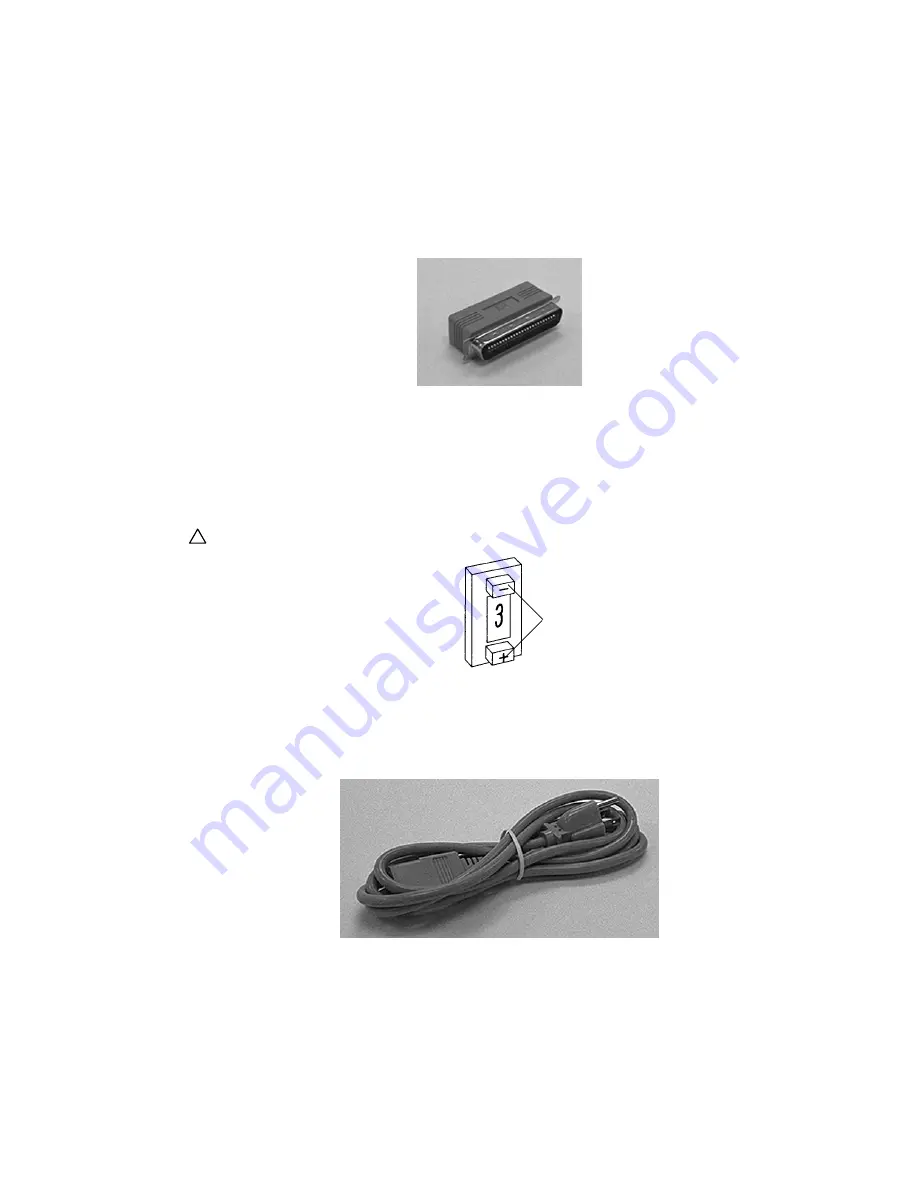
If the DataDock is the only device on the SCSI bus, connect the supplied active terminator to the
unused SCSI connector on the rear of the DataDock, otherwise daisy chain the additional SCSI
devices to the DataDock’s open SCSI connector and connect an active terminator to the last device
in the chain.

Terminator (Narrow).

6.

Set the SCSI ID switches on the rear of the DataDock to ID numbers that are not in use by
other SCSI devices on the same bus. The SCSI ID number is changed by pressing the switch’s
push buttons.

In Macintosh systems, ID 0 and 3 are usually assigned to the internal hard disk and CD-ROM drive,
respectively. In IBM PC systems, ID 0 and 1 are usually reserved for boot drives. In both systems, ID 7 is
reserved for the system and cannot be used.

!

Two SCSI devices sharing the same SCSI ID will cause problems to occur.

SCSI ID switch.

7.

Ensure the DataDock’s power switch is in the off position (“0” pressed inwards), then connect the
supplied power cord from the DataDock to a grounded outlet.

The universal power supply in the DataDock automatically adjusts to any input from 90 to 240 volts and
any frequency from 50 to 60 Hz, so no adjustment is necessary.

AC Power cord.

Push button selectors

Summary of Contents for DataDock 350

Page 1: ...1 Part Number MA1036 Rev D Copyright 1996 by MicroNet Technology Inc Printed in the U S A November 1996 DataDock Storage Systems User s Guide ...

Page 2: ...se emissions for digital apparatus set out in the Radio Interference Regulation of the Canadian Department of Communications Operation in a residential area may cause unacceptable interference to radio and TV reception requiring the owner or operator to take whatever steps are necessary to correct the interfer ence Conformité aux règiements du Départment Canadien de Communications Cet équipement n...

Page 3: ...ation and the software described within may not in whole or part be copied photocopied reproduced translated or reduced to any electronic medium or machine readable form without prior consent in writing from MicroNet MicroNet cannot guarantee you will receive revision notices for the software described in this manual even if you have returned a registration card Periodically check with your resell...

Page 4: ...e consult the User s Guide that was supplied with your computer system Your computer dealer and local user s groups are also good sources of information After you are comfortable with the operation of your computer continue reading this manual which describes hardware installation and software operation Thank you again for choosing a MicroNet Technology system Please fill out the enclosed registra...

Page 5: ...How to use the DataDock Supported Modules 20 Using Hard Disk Modules 20 Using Removable Media Modules 22 Using Software 24 Section 3 Features DataDock Front Panel 25 DataDock Rear Panel 26 DataDock Mode Settings 28 Hard Disk Module Front Panel 29 DataDock Module Rear Panel 30 Section 4 Maintenance Care Maintenance and Care 31 Section 5 Troubleshooting Problems Solutions 32 Getting Help 33 ...

Page 6: ...isters your subsystem in our database and provides us with helpful information This information is not sold or distributed System Requirements MicroNet DataDock storage systems are compatible with Macintosh IBM compatible SGI and Sun computers Choosing a Location Place the DataDock unit in its permanent operating location near the computer DataDock desktop systems are designed to operate on a hori...

Page 7: ... one SCSI cable path or channel connecting it to the computer This cable connects to the computer s SCSI port or the external SCSI connector of a SCSI adapter card installed in the computer A dual channel installation is one where the DataDock unit has two SCSI cables channels connecting it to the computer You can create two separate SCSI buses using 2 single channel SCSI cards 1 dual channel SCSI...

Page 8: ...d to a Macintosh otherwise set it to position 1 DataDock rear panel Narrow 3 If the DataDock will be connected to a Macintosh connect the small end of the supplied 25 to 50 pin SCSI cable to the SCSI port on the rear of the Macintosh then connect its opposite end to the bottom SCSI connector on the rear of the DataDock 4 If the DataDock will be connected to a SCSI card connect the high density end...

Page 9: ...itch s push buttons In Macintosh systems ID 0 and 3 are usually assigned to the internal hard disk and CD ROM drive respectively In IBM PC systems ID 0 and 1 are usually reserved for boot drives In both systems ID 7 is reserved for the system and cannot be used Two SCSI devices sharing the same SCSI ID will cause problems to occur SCSI ID switch 7 Ensure the DataDock s power switch is in the off p...

Page 10: ... Macintosh computer this completes installation To complete DataDock installation for Sun SGI and IBM compatibles refer to the DataDock for your operating system supplements These supplements describe how to properly configure the system and prepare DataDock modules for use in your environment If you intend to regularly use a re writable disk cartridge such as a Jaz SyQuest or re writable optical ...

Page 11: ...s are external devices connected to the computer such as modems printers scanners and SCSI devices 2 Set the DataDock s mode switch to position 2 if it will be connected to a Macintosh otherwise set it to position 1 Wide DataDock rear panel 3 Connect one end of the MicroNet supplied SCSI cable to the SCSI card s connector and the other to the bottom SCSI connector on the rear of the DataDock 68 to...

Page 12: ...minator to the last device in the chain 6 Set the SCSI ID switches on the rear of the DataDock to ID numbers that are not in use by the other SCSI devices on the same bus The SCSI ID number is changed by pressing the switch s push buttons In Macintosh systems ID 0 and 3 are usually assigned to the internal hard disk and CD ROM drive respectively In IBM PC systems ID 0 and 1 are usually reserved by...

Page 13: ...adjustments are necessary AC power cord 8 Turn on the DataDock power switch then insert a DataDock module into each DataDock bay that you intend to use The POWER indicator on the DataDock s front panel will illuminate and the TEMP alarm will flash and beep once to indicate that it is functioning correctly The module will automatically latch into place and power up The triangular button for the mod...

Page 14: ...tem and prepare DataDock modules for use in your environment If you intend to regularly use a re writable disk cartridge such as a Jaz SyQuest or re writable optical in the DataDock it is recommended that you prepare the cartridge with DataDock compatible disk utility software This prevents long term mounting problems In Macintosh applications re writable disks can be prepared using the MicroNet U...

Page 15: ...witch to position 2 if it will be connected to a Macintosh otherwise set it to position 1 Wide DataDock rear panel 3 Remove the cover and jumper cable beneath it from the two middle SCSI connectors on the rear of the DataDock To remove the cover loosen and remove its four retaining screws by turning them in a counterclockwise direction using a Phillips head screwdriver For model DD and DD525 DataD...

Page 16: ...CSI bus connector The first SCSI bus connector can be the computer s SCSI port or the SCSI port of the adapter card Some possible SCSI bus connectors include Computer s built in SCSI port Internal bus Connector of a Dual channel SCSI card Connector of a Single channel SCSI card Many configurations are possible examine the following diagrams ...

Page 17: ...lly only necessary to terminate the last SCSI device connected to each SCSI bus Wide terminator Narrow terminator 7 Set the SCSI ID switches on the rear of the DataDock to the same SCSI ID number Make sure that the number is not in use by any other SCSI device on the same bus The SCSI ID number is changed by pressing the switches push buttons In Macintosh systems ID 0 and 3 are usually assigned to...

Page 18: ... Hz so no adjustment is necessary AC power cord 9 Turn on the DataDock power switch then insert a DataDock module into each DataDock bay that you intend to use The POWER indicator on the DataDock s front panel will illuminate and the TEMP alarm will flash and beep once to indicate that it is functioning correctly The module will automatically latch into place and the drive will power up The triang...

Page 19: ...ck modules for use in your environment If you intend to regularly use a re writable disk cartridge such as a Jaz SyQuest or re writable optical in the DataDock it is recommended that you prepare the cartridge with DataDock compatible SCSI utility software This prevents long term mounting problems In Macintosh applications re writable disks can be prepared with the MicroNet Utility software using t...

Page 20: ...25s using the DataDock 525 adapter accessory This item is sold separately and can be ordered from your authorized MicroNet dealer Using Hard Disk Modules This section is a guide for using the hard disk modules with your DataDock unit Starting up the Computer 1 Turn on the DataDock and insert its modules 2 Allow the modules time to spin up 3 Turn on other peripherals connected to the computer and a...

Page 21: ...inking and glow steadily 4 Wait for the hard disks to be recognized by the system The hard disk will be recognized by the system if a DataDock fixed or removable disk module was inserted in the unit s bay and powered up before system start up If the hard disk is not recognized mount it using DataDock compatible software or by restarting the computer Macintosh When a DAT module is removed from the ...

Page 22: ...es connected to the computer such as scanners modems printers and SCSI devices 4 Turn on the computer If you intend to regularly use a re writable disk cartridge such as a Jaz SyQuest or re writable optical cartridge in the DataDock it is recommended that you first prepare the cartridge with DataDock compatible disk utility software This prevents long term mounting problems In Macintosh applicatio...

Page 23: ...ext to the module on the DataDock unit s front panel 3 When the triangular button is no longer lit swing up the module s handle and gently pull the module out of the unit Removing a removable media drive module Inserting a Module in the DataDock 1 If you have not done so already turn on the DataDock unit 2 Insert the module into the DataDock unit Inserting a Removable Media Module 3 Allow the modu...

Page 24: ...and hard disk drive modules When preparing hard disk modules with the MicroNet Utility only use version 6 9 5 or above If the cartridge was prepared with an earlier version of the utility use the Reinstall Drivers feature to update its drivers Earlier versions of MicroNet Utility will not support the DataDock s features Remove any SCSI mounting extension INITS such as the MicroNet Cartridge Extens...

Page 25: ...utton light is blinking the module is powering up or down When a button light is lit solid the module is powered up and ready for use The DataDock automatically adapts to the type of module inserted As an example a DAT module will power up or down in only a few seconds while a high performance disk drive module may require 20 seconds to do so Bay doors The doors on the front of the DataDock automa...

Page 26: ...o the computer allows the computer to communicate with the DataDock unit and its modules SCSI ID switches These two switches are push button type selector switches They are used to change the SCSI ID number assigned to the modules inserted in the DataDock The top switch is for setting the SCSI ID number of the upper bay and the bottom switch is for setting the SCSI ID number of the lower bay SCSI ...

Page 27: ...se levers can be used to unlock a module from the DataDock while the DataDock is powered off Modules are mechanically latched into place when inserted in the DataDock The latches are electrically operated so when power is off you must use the emergency module release levers instead of the drive control buttons to remove modules from the DataDock To remove a module push the lever toward the center ...

Page 28: ...at the drive is ready to use If the software driver for the module is memory resident has been loaded before the drive will automatically mount If the driver is not memory resident the media can be mounted using software or by restarting the computer Removal of a hard drive module is also software controlled On a Macintosh for example when the drive s icon is dragged into the Trash the drive autom...

Page 29: ...lots on the sides of the drive module support and guide the modules as they are inserted into the DataDock The guide slots are designed to prevent modules from being inserted upside down Job label Located on the right side of the DataDock handle the job label can be used to identify what data is stored on the hard drive A package of three labels is supplied with each module These labels have a sem...

Page 30: ...e module are discharged before any signal pins mate preventing damage to electronic components due to electrostatic discharge ESD After all power and signal pins have mated the final pin mates to tell the DataDock control electronics that the connector is completely engaged and that it is safe to begin the power up sequence Connector shroud The shroud around the module connector provides protectio...

Page 31: ...extreme temperatures or high humidity These sources can erase or corrupt data When cleaning your DataDock unit only use a soft cloth slightly moistened with water Do not apply lubricants or blow air into the DataDock unit Never connect or disconnect a SCSI cable or terminator while the computer and its other peripherals are turned on This may damage the DataDock and or the computer Keep the area a...

Page 32: ...receiving power Make sure you inserted the module completely Press firmly when inserting a module until you feel or hear it lock into place Modules aren t seen by the system Make sure the module is powered on and ready for use then restart your computer Reinstall the module s SCSI driver using a DataDock compatible disk utility Carefully inspect for a loose cable or terminator Review the installat...

Page 33: ...If the fan is not operating turn off the DataDock and contact MicroNet Technical Support Check that the air vent slots at the front and side of the DataDock are free from obstruction Remove each module to see if the temperature alarm stops If the alarm stops as a module is removed the module is too hot If the alarm continues to sound after both modules are removed the DataDock itself is too hot Tu...

Reviews: