Microcyber G0310 User Manual Download Page 20

http://www.microcyber.cn/en

~ 15 ~

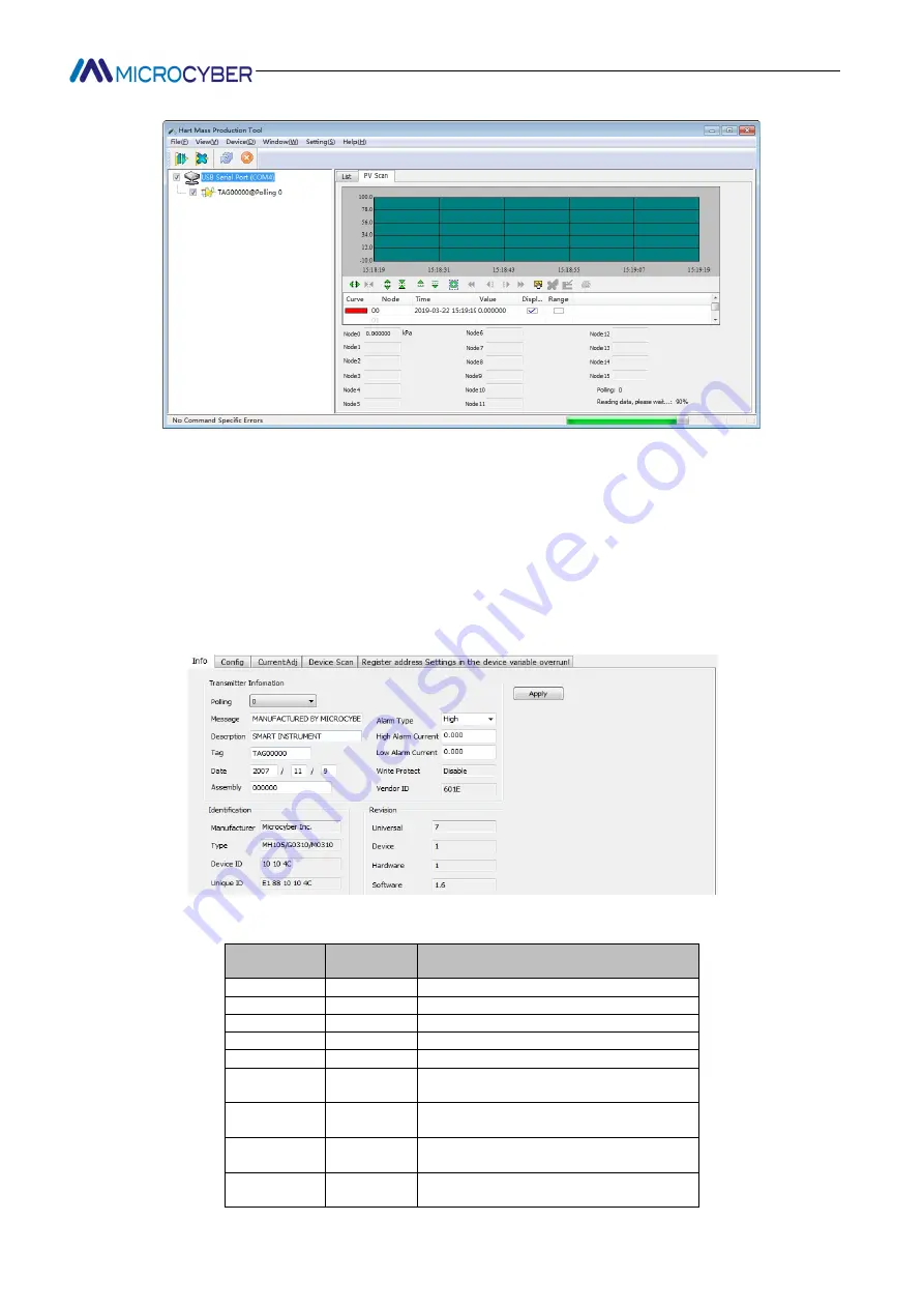
Figure 5.19 Main variable monitoring tab

iii.

Basic Info

Users can obtain and configure basic information about online devices.

Method to access the Basic Information tab:

(1) The left mouse button clicks on an online device in the network view, and the right tab view displays the

tabs associated with the device.

(2) Click "basic information" in the right tab view, and if the information is obtained successfully, the basic

information of the device is displayed, as shown in Figure 5.20.

Figure 5.20 Basic information tab

The basic information tab contains the following table:

Functional

description

Whether to

modify

Remarks

Address

Yes

polling address, selection range 0~15

Message

Yes

Up to 32 characters

Description

Yes

Up to 16 specified characters

Label

Yes

Maximum length of 8 specified characters

Date

Yes

From 1900 to 2155

Assembly

Number

Yes

Must be 6 decimal places

Alarm

selection

No

Display hardware alarm selection mode ," high

alarm "/" low alarm "

Writing

protection

No

Display hardware write protection options, NO

"/" YES"

ID

of

manufacturers

No

Trademark issuer code, hexadecimal

Summary of Contents for G0310

Page 1: ...G0310 Modbus to HART gateway User Manual...

Page 2: ...http www microcyber cn en I Warning 1 Please don t take off install gateway at random 2 Please check if the power of temperature board set meets the power request in the User Manual...

Page 3: ...xplosion proof and safety barrier Also Microcyber participated in the drafting of the domestic first Ethernet based industrial automation protocol standards Ethernet for Plant Automation EPA As a resu...

Page 4: ...evice variable assignment 24 5 5 5 Modbus variable configuration 25 5 5 5 1 Address 25 5 5 5 2 baud rate 25 5 5 5 3 Data bits 26 5 5 5 4 Calibration 26 5 5 5 5 Stop Bits 26 5 5 5 6 CRC byte order 26 5...

Page 5: ...http www microcyber cn en IV Chapter 8 Technical Specification 35 Chapter 9 Appendix1 G0310 MODBUS to HART Gateway Model Selection 36...

Page 6: ...HART Gateway communicates with devices that have Modbus RTU communication function via RS485 interface It can convert device data to HART device variables output and it also supports 4 20mAcurrent out...

Page 7: ...lectromagnetic interference ability G0310 MODBUS to HART gateway connection diagram is shown as in Figure 2 2 24VDC Power PC HART Modem Resistance 5 6 1 2 9 10 Ampere meter Modbus device RS485 communi...

Page 8: ...ng it will compare PV and range upper and lower limiting value constantly When PV exceeds the limit instrument will output fixed current When PV is higher than upper limit it output 20 8mA When PV is...

Page 9: ...to dynamic variable as the device output supporting 4 20mA analog signal output G0310 MODBUS to HART Gateway functional block diagram is shown as Figure 3 1 MODBUS REGISTER MODBUS Device Configure In...

Page 10: ...coil calibration 1 read coil 2 read discrete input 3 write single coil register calibration 1 read hold register 2 write register variable configuration 1 sensor configuration 2 variable configuration...

Page 11: ...1 HART Point to point connection Features 1 It can be connected to the upper control system through the AI input module or HART communication device 2 Mixing of analog and digital communications 3 De...

Page 12: ...are of G0310 is design and development by Microcybe the installation method is shown as follow 1 First double click to install the setup as shown in the Figure 5 3 Figure 5 3 setup 2 Click next to the...

Page 13: ...tion Figure 5 7 installed The HARTMPT icon will appear on the desktop after the installation is complete as shown in the Figure5 8 Figure 5 8 PC software After the installation is complete it goes dir...

Page 14: ...interface 1 Menu Bar 2 Toolbar 3 Network view 4 Tabular View 5 Alarm window 6 Status bar The following outlines the functions of each part i Menu Bar File F The user executes the menu File exit or cli...

Page 15: ...ion port is serial port 1 COM1 ii Tool Bar As shown in Figure 5 10 the toolbar contains four functions searching online devices stopping searching devices refreshing and stopping refreshing Figure 5 1...

Page 16: ...y accessed device vi Status bar Displays the status of the current operation according to the operation 5 3 Basic operations i Set up serial port When starting the default communication port is serial...

Page 17: ...n the serial node of the network view and select a single node a node for example node 0 Figure 5 14 Right click convenient search menu Full search Click the right mouse button on the serial node of t...

Page 18: ...adecimal Figure 5 16 send command Sending commands requires understanding the frame format of each command so it is only applicable to senior users and R D personnel iv Multilingual support The config...

Page 19: ...k of all online device related tab information 2 Click on the device list in the right tab view and if the information is obtained successfully the summary information of all searched online devices i...

Page 20: ...tion of the device is displayed as shown in Figure 5 20 Figure 5 20 Basic information tab The basic information tab contains the following table Functional description Whether to modify Remarks Addres...

Page 21: ...d configure the configuration information of online devices Method to access the Configuration Information tab 1 The left mouse button clicks on an online device in the network view and the right tab...

Page 22: ...y modify the value of the upper or lower range limit and press the Application button to download the information to the device Set range upper and lower limits with current values Range Upper Limit S...

Page 23: ...according to the PV value Configure current fixed output The user can configure the fixed current output in the current calibration tab enter the output fixed current value in the fixed current value...

Page 24: ...hown in Figure 5 23 Figure 5 23 Variable Monitoring tab 5 5 Gateway Parameter Setting 5 5 1 Mode selection 1 Left click on an online device in the network view and the right tab view displays the tabs...

Page 25: ...example select configuration mode as shown in Figure 5 25 Figure 5 25 Operating Mode Settings 5 5 2 Coil calibration Coil read and write the user can choose calibration coil and make the coil input re...

Page 26: ...he Calibration Register read hold register to pop up the register window as shown in Figure 5 29 Figure 5 29 Read register input 2 Enter register address and length value please note that the range of...

Page 27: ...he system prompts set up successfully then clicks OK to complete the operation Figure 5 33 Returns to factory default settings prompt 5 5 4 2 Save to factory settings 1 Click the Calibration restore f...

Page 28: ...5 5 4 3 Reset to factory settings 1 Click the Calibration restore factory settings restore to factory settings pop up restore to factory settings window as shown in Figure 5 37 Figure 5 37 Reset to fa...

Page 29: ...an be mapped to 4 dynamic variables according to demand For example map the main variable to device variable 4 1 Select the detailed design device variable assignment device variable assignment corres...

Page 30: ...in Figure 5 43 Figure 5 43 Modbus Address settings 2 Enter a modified value with an address worth range of 1 255 Then click apply to save the modified value 5 5 5 2 baud rate 1 Select detailed Design...

Page 31: ...check as shown in Figure 5 46 Figure 5 46 Modbus Selection of calibration values 2 Select the value that needs to be modified then click the apply button to save the modified value 5 5 5 5 Stop Bits...

Page 32: ...vice Status Configuration 5 5 6 1 Register address 1 locate the detailed design device status the input box corresponding to the register address the range of the register address is 1 65536 as shown...

Page 33: ...below 1 Select Detailed Design PV range the drop down box corresponding to register data type as shown in Figure 5 54 Figure 5 54 Selection of register data type 2 Select the value that needs to be m...

Page 34: ...etailed Design Sensor drop down box corresponding to Sensor range limit as shown in Figure 5 58 Figure 5 58 Upper Range Selection of Sensor Range 2 Enter the modified value then click apply to save th...

Page 35: ...e 5 61 Figure 5 61 Upper Range Selection 2 Enter the modified value then click apply to save the modified value 5 5 8 7 Lower range limit 1 Select the detailed design sensor drop down box correspondin...

Page 36: ...address 1 Select Detailed Design Sensor drop down box corresponding to Register address as shown in Figure 5 65 Figure 5 65 Register address selection 2 Enter the modified value then click the apply b...

Page 37: ...ress as shown in Figure 5 68 Figure 5 68 Address Selection of Range Upper Limit Register 2 Enter the modified value then click the apply button to save the modified value 5 5 8 14 Range Lower limit re...

Page 38: ...can use this step to configure otherwise you can not configure The Device Status parameter contains Register Address and Bit Mode where Register Address indicates the register location of the device...

Page 39: ...eck network 5 485Power supply 24V Power light off a Power failure b Wire open circuit c internal failure a Repair the power b Check the wire c Contact technical support 6 HART communication light off...

Page 40: ...ance Requirements for Industrial Places in General Requirements HART Port Test Methods Electromagnetic Compatibility Requirements for Electrical Equipment GB T 18268 23 2010 Measurement Control and La...

Page 41: ...to HART Gateway Model Selection Type Selection List G0310 Modbus to HART Gateway Code code Hardware interface R4 could be omitted RS485 Code code Software interface MR M could be omitted Modbus RTU M...

Page 42: ...E R CO R P O R AT I O N Microcyber Corporation Http www microcyber cn en Add 17 8 Wensu Street Hunnan New District Shenyang China 110179 Tel 0086 24 31217278 31217280 Fax 0086 24 31217293 Email sales...

Reviews: