


Object Dictionary
CANopen Protocol
μCAN.8.dio-BOX
MicroControl Version 2.00
Page
56
8
8.4.3 Manufacturer Specific Objects
In this section you will find all manucaturer specific indices for the
μCAN.8.dio-BOX
Tabelle 12: Manufacturer specific objects
Index
Name
5FF5
Port Direction
Port Direction
Index 5FF5h
The object at index 5FF5h is used to modify the port direction of
each terminal.
Sub-Index
Data Type
Acc
Name
Default Value
0
Unsigned8
rw
Port direction
00h
Only sub-index 0 is supported. An access to other sub-indices will
lead to an error message. Writing a ’1’ will define the terminal as
output.
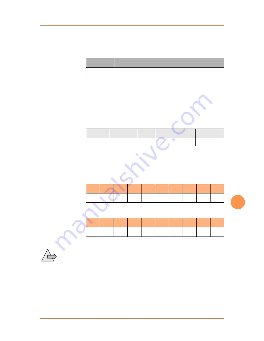
Beispiel:
Configure terminals 1 - 4 as outputs
ID
DLC
B0
B1
B2
B3
B4
B5
B6
B7
601h
8
22h
F5h
5Fh
00h
0Fh
00h
00h
00h
As result the μCAN.8.dio-BOX will send the following message:
ID
DLC
B0
B1
B2
B3
B4
B5
B6
B7
581h
8
60h
F5h
5Fh
00h
00h
00h
00h
00h
By default all terminals are configured as digital inputs. The out-
puts
Note
can only be set, if they have been configured properly with
the object 5FF5h.


