


CAN Bus
Installation
μCAN.8.dio-BOX
MicroControl Version 2.00
Page
26
5
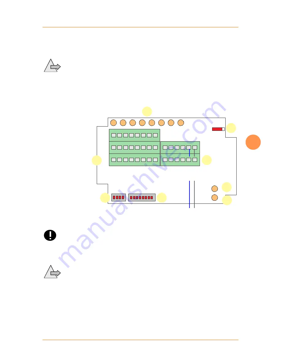
5.4 CAN Bus
The two wires of the CAN bus are connected to the appropriate
terminals.
To
Note
reduce the influence of EMI please take care that the CAN bus
cable does not cross the wires of the signal lines.
The CAN bus line with positive potential must be connected to
the terminal
CAN_H
. The CAN bus line with negative potential
must be connected to the terminal
CAN_L
.
Modul ID
Baud
Term
Off/On
CAN_H
CAN_L
GND
V+
V-PWR
V+PWR
I/O_1
I/O_2
I/O_3
I/O_4
I/O_5
I/O_6
I/O_7
I/O_8
NS
MS
1
2
4
3
6
5
7
8
CAN bus
Abb. 7: Connection of CAN bus
If you confuse the poles the communication on the bus will not
be possible. The
Attention !
shield of the CAN bus may not lead into the hou-
sing and may not be connected to a terminal inside the housing.
Cable shields have to be connected to the terminals outside the
housing.
If you use a Sub-D connector with 9 pins (according to CiA stan-
dard), the
Note
conductor
CAN_H
is connected to pin 7 and the con-
ductor
CAN_L
is connected to pin 2.


