24
The AREA, DISTANCE and VOLUME counters maintain a
running count during operation regardless of the position
of the rotary switch. When any of these counters reach their
maximum capacity, or when you want to start a new count,
the value may be reset to zero by performing the following
steps. Counters may be reset independently of each other.
1. Turn the Run/Hold switch to Hold.
2. Turn the rotary switch to the counter to be reset.
3. To reset distance turn the rotary switch to DISTANCE,
press and hold the RESET button until the display reads
zero. The display will show the word “CLEAr” during this
process, and will show 0.0 when reset is complete.
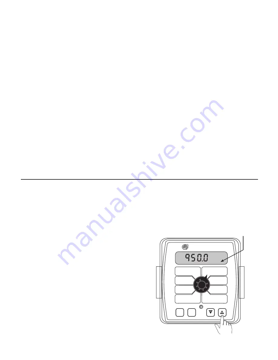
4. To reset the volume and area counters; there are three
independent AREA counters, paired with three VOLUME
counters. The active pair of counters is indicated by the
small numbers in the lower right area of the display (1,2,
or 3) when the rotary switch is in the AREA or VOLUME
position. Select the pair of counters you want to use by
pressing the “+” button. The small number will increment
each time the “+” button is pressed (from 1 to 3, then rolls
back to 1). DO NOT attempt to select the counter number
by using the “-” button, because that will clear the active
pair of counters if held for 2 seconds. If the “-” button is
MT-NH3 II
™
AUTO
MAN
CAL
RESET
RATE
ACTUAL “N”
TOTAL NH3
(1) (2) (3)
AREA
(1) (2) (3)
NH3 PER
MINUTE
TANK (NH3)
DISTANCE
AREA/
HOUR
SPEED
FLOW
CAL
MIN
FLOW
ADJUST
RATE
TARGET
RATE
WIDTH
CAL
SPEED
CAL
1
Display indicates which counter pair is selected
Console Operation
(cont)
Resetting System Counters
Erratic application rate
1.
Start applying and when your rate is close to your
target, select the gallons per minute, or lbs per minute
display on your controller. This is the reading directly off
the flowmeter. Place the controller in MANUAL. This stops
movement of the control valve. If the rate stabilizes the
erratic operation is most likely induced by the control
system.
Possible Solutions:
A.
Set the VALVE CONTROL SPEED to a lower setting.
Negative values slow down the response of the valve,
positive numbers make the response more aggressive.
Typical control speed values for NH3 application are -2 to -4,
but vary by installation.
B.
Verify adequate manifold pressure. Manifold pressure is
very important for smooth control and even distribution
of NH3. Use barbed fittings with properly sized orifices or an
adjustable manifold to maintain adequate pressure. If
manifold back pressure is too low, the only resistance to the
flow of NH3 is the control valve. At lower rates, this will
result in the control valve operating almost fully closed. This
results in erratic control since the flow through the valve
can vary greatly with minimal movement. Adequate back
pressure allows the valve to operate in a more open
position which results in stable application rates. Typical
manifold pressure ranges from 15 to 60 PSI (1 to 4 bar)
depending on application rates and ambient temperature.
2.
If the rate continues to bounce around while in MANUAL,
vapor may be entering the flowmeter. Any obstruction
(clogged filter, partially closed tank valve, plugged tank dip
tube) can cause a pressure drop which will in turn generate
large amounts of vapor.
Possible Solutions:
A. If the rate in MANUAL is varying by a small amount (10
- 20 lbs per acre) this may indicate worn bearings in the
flowmeter.
B. Verify the vapor line and vapor control orifice are clean
and free of obstruction.
C. Verify the strainer is clean.
Poor System Performance
In NH3 control systems, location of the frost build-up is an
indication of system performance. The NH3 kit will normally
have frost on the output side of the servo valve and on
the bottom portion of the heat exchanger. Frost before
the servo valve or on the flowmeter indicates vapor in the
system as a result of excessive pressure drop (caused by
obstructions) in the delivery system, restricted vapor lines or
clogged vapor control orifice.
The strainer is a common source of excessive pressure drop
and should be cleaned regularly. AFTER COMPLETELY
DRAINING THE SYSTEM, remove the large plug and
carefully clean the strainer screen.
Also, periodically check the vapor tubes for obstructions.
Field Operation
accidentally pressed, the console will display “CLEAr” to
alert the user that the counters will be cleared. If the user
continues to hold the “-” button for 2 seconds “CLEAr”
will disappear and be replaced by 0.0, indicating that the
selected pair of counters has been cleared.


