


Page 8
Functional Principle, Technical Data
optoNCDT ILR2250
3.
Functional Principle, Technical Data
3.1
Short Description
The optoNCDT ILR2250 is a laser distance measuring device that precisely measures distances in the range of 0.05 m to
150 m without contact. The measurement target can be clearly identified by the red laser measuring point. The maximum
range depends on the reflectivity and surface properties of the target.
The device works on the basis of phase comparison measurement. High-frequency modulated laser light is emitted in
the process. The light diffusely reflected and phase-shifted by the measuring object is compared with the reference sig-
nal. The magnitude of the phase displacement makes it possible to determine the distance to the nearest millimeter.
The distance measurement can be started in various ways:
-
A command can be sent by a PC or another control unit via a serial RS422 interface
-
External triggering
-
Using the autostart function
3.2
Measuring Principle
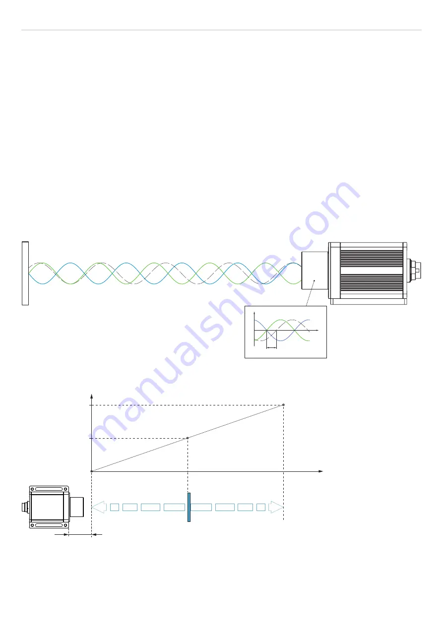
Light in the visible wavelength range is modulated with suitably chosen frequencies such that the exact distance can
be derived from the multiple of the relevant modulation wavelength contained in the distance to be measured and from
the size of the remaining interval. The remaining interval is measured using analog phase comparison methods. Several
modulation waves are used to determine the distance.
t
1
t
2
1
0
t
Target
Fig. 2 Evaluation of the phase displacement for determining the distance
3.3
Term Definitions, Analog Output Displacement
SMR
20 mA
12 mA
4 mA
Target
Measuring range (MR)
SMR
EMR
Displacement
Signal
ILR2250
SMR
Start of measuring range, minimum distance between sensor and target
EMR
End of measuring range (start of measuring range + measuring range),
maximum distance between sensor and target
MR
Measuring range


