7 SG9H 70 en
15
4.4.2 MAN
It is possible to control the valve position from the keyboard in
the Manual Mode. To do this, you must return to Measurement
Monitoring Menu (main menu).
Choose
TPOS
and press
?
. In the upper row
TPOS
starts to blink and in the lower row you can see the
current position of the valve.
CLO
= valve closed
OPE
= valve open
--- = valve is somewhere between open and closed
positions.
You can control the valve position as follows:
+
Opens the valve, "---" blinks during movement.
-
Closes the valve, "---" blinks during movement.
Blinking stops when the valve is again fully open or
closed.
4.5
Configuration parameters
When
PAR
is on the display you may enter the configuration
menu by pressing the
?
key. In this menu the most important
configuration and signal modification parameters are viewa-
ble. You may view the current value and edit them by pressing
the
?
key at the relevant parameter. The name of the param-
eter will appear on the upper row of the display and the cur-
rent value is on the lower row. See also table in Chapter 13.
4.5.1 Stroke time and profile,
STOP
,
STCL
,
SPOP
,
SPCL
Valve open and close profiles can be configured with Neles
SwitchGuard with the limitation set by valve assembly.
Stroke time performance constraints can be seen from the
piping table in Section 3.4. Both stroke directions can be set
without any connection to the each other.
Opening and closing times can be set with
STOP
(open)
and
STCL
(close) parameters. Parameter is given in sec-
onds.
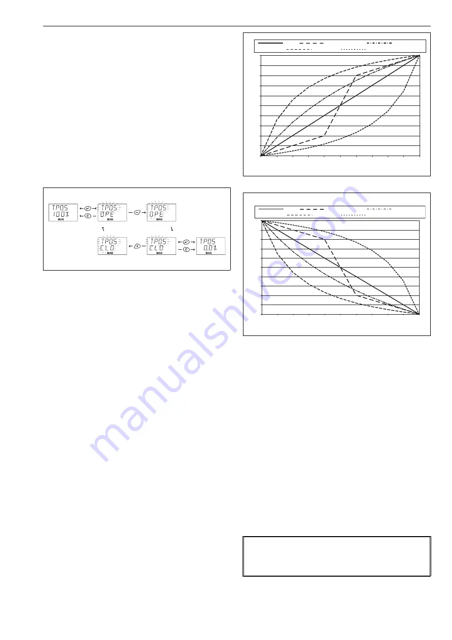
Used stroke profile shape can be set with parameters
SPOP
(open) and
SPCL
(close). Profile can be chosen separately
for both direction from one of the five profile shapes: Linear
(1), Slow Starting (2), Slow Starting & Ending (3), Equal Per-
centage (4) and Quick Starting (5). If valve stroke is needed
to do as fast as possible, set time stroke time to 0.
4.5.2 Trigger level,
LEV
Input setpoint level to start position transition. A fixed hys-
tereris is applied on this level (trigger level – 5 %). Default
value is 50.0 % (12 mA) and range is 20...80 % (7.2 mA...16.8
mA).
4.5.3 Signal direction,
DIR
The opening and closing direction of the valve with raising
current loop signal is defined by signal direction parameter
DIR
.
When
DIR
is displayed press the
?
key to enter the
edit state and
DIR
starts to blink.
Select either the
OPE
or
CLO
values by pressing the
+
and
-
keys. The value
OPE
signifies the raising
signal 4–20 mA to open the valve and
CLO
means
the raising signal to close the valve.
To conclude, press the
?
key when the desired
value is shown on the display.
See default values in Fig. 5.
Fig. 12
Setpoint change in MAN mode
Fig. 13
Stroke profile shapes, opening
Fig. 14
Stroke profile shapes, closing
NOTE:
In case of signal direction (DIR) is same than Positioner Fail
Action (PFA) 5 mA input signal is recommended as mini-
mum.
0
10
20
30
40
50
60
70
80
90
100
0
10
20
30
40
50
60
70
80
90
100
Linear
Slow Starting & Ending
Equal Percentage
Quick Starting
Slow Starting
% of stroke time
valv
e tra
v
el
0
10
20
30
40
50
60
70
80
90
100
0
10
20
30
40
50
60
70
80
90
100
Linear
Slow Starting & Ending
Equal Percentage
Quick Starting
Slow Starting
% of stroke time
valve travel


