


7 AMI 70 en
5
1.4
CE marking
The limit switch meets the requirements of the Euro-
pean Directives and has been marked according to the
Directive.
1.5
Recycling and disposal
Most limit switch parts can be recycled if sorted
according to material. See the list below for materials.
In addition, separate recycling and disposal instruc-
tions are available from us. A limit switch can also be
returned to us for recycling and disposal against a fee.
1.6
Safety precautions
2
ASSEMBLY AND MOUNTING
Neles Axiom mounting kits are sold separately.
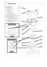
1. Refer to Axiom Assembly Drawing located in Section
4 when performing mounting and assembly proce-
dures.
2. Remove Axiom unit from shipping container. Ensure
all listed items are present.
3. With an M4 allen wrench, loosen the four captive
Axiom Cover Screws (Item# 1), remove cover.
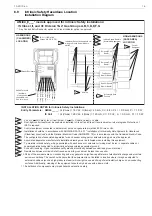
4. Determine if the actuator the Axiom is to be mounted
on is double acting (DA) or spring return (SR). Flip
the Axiom body (Item# 4) over and ensure the DA/SR
Plug (Item# 5) is in the correct position. (See Detail -
A in Section 4). If the DA/SR Plug is in the incorrect
position, gently remove plug with a pair of pliers and
insert into the proper hole.
5. From the mounting kit package, locate the Air Mani-
fold Plate (Item# 14). Place the Air Manifold Plate on
the actuator. Using an M4 allen wrench, fasten down
with the four Air Manifold Mounting Screws (Item#
11). Torque screws to 2.8 - 3.4 Nm.
6. Place Visual Indicator Drive Block (Item# 10) into slot
on the actuator shaft. Place Visual Indicator Drum
Coupler (Item# 8) onto the Visual Indicator Drive
Block. Next, place the Visual Indicator Drum (Item#
7) onto the Visual Indicator Drum Coupler. Align the
holes in all three items with the the threaded hole in
the actuator shaft and fasten down with the Visual
Indicator Drum Retaining Screw (Item# 9). Leave
screw loose in order to facilitate indexing of the vis-
ual indicator.
7. With the actuator in the closed position, center the
Visual Indicator Drum until the “OPEN” quadrant is
centered between the “V.I INDEX” markings on the
AIr Manifold Plate. (See Detail - B in Section 4).
Tighten down with the Visual Indicator Drum Retain-
ing Screw 1.7 - 2.3 Nm.
NOTE:
In high cycle or high vibration applications,
blue Loctite® may be used on the Air Manifold
Mounting Screws (Item# 11) and the Visual Indicator
Drum Retaining Screw (Item# 9).
8. Verify Air Manifold Plate Orifice O-rings (Item# 12)
and Visual Indicator Cover O-ring (13) are in place.
9. Place the Visual Indicator Cover (Item# 6) over the
Visual Indicator Drum assembly then set the Axiom
Body (Item# 4) in place. With an M4 allen wrench,
torque the Axiom Body Screws to 2.8 - 3.4 Nm.
10.After all wiring and sensor setting procedures have
been completed, install Axiom Cover and torque
Axiom Cover Screws to 1.7 - 2.3 Nm.
CAUTION:
Do not exceed the permitted values!
Exceeding the permitted values marked on the limit
switch may cause damage to the switch and to equip-
ment attached to the switch and could lead to uncon-
trolled pressure release in the worst case. Damage to
the equipment and personal injury may result.
CAUTION:
To prevent ignition of hazardous atmospheres,
replace cover before energizing the electrical circuits.
Keep cover tightly closed when in operation.
NOTE:
To mount the Axiom requires a mounting kit specific to
the actuator the Axiom is to be mounted to.