


18
7 AMI 70 en
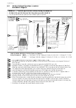
6.12
Intrinsic Field Wiring Apparatus
Installation Drawing
INSTALLATION NOTES:
AMI93__ Entity Parameters (FISCO):
Ui(Vmax) = 30Vdc; Ii(Imax) = 380mA ; Ci = 0.0nF; Li = 0.0mH; Pi = 5.32 W
Outputs:
Uo = 7.14Vdc; Io = 47mA; Po = 0.1W
1. Installation shall be in accordance with ANSI/ISA RPA12.6.01, ANSI/NFPA 70, and the National Electrical Code or in accord-
ance with the Canadian Electric Code.
2. Dust-tight conduit seal must be used when installed in Class II and Class III environments or where Ingress Protection of
IP67 is required.
3. Control equipment must be FISCO Approved Associated Apparatus.
4. Control equipment connected to FISCO barrier must not use or generate more than 250Vrms or Vdc.
5. Resistance between FISCO Intrinsically Safe Ground and earth ground must be less than 1.0 Ohm.
6. Parts of the enclosure are non-conducting and may generate an ignition-capable level of electrostatic charge under certain
extreme conditions. The user should ensure that the equipment is not installed in location where it may be subjected to
external conditions (such as high-pressure steam) which might cause a build-up of electrostatic charge on non-conducting
surfaces. Additionally, cleaning of the equipment should only be done with a damp cloth.
7. Substitution of components may impair hazardous location safety.
8. Approval Agency controlled Installation Diagram. No revision to diagram allowed without prior Factory Mutual or Approval
Agency authority.
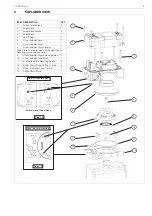
3
4
2
1
5
6
AMI93_A___* models approved for Intrinsic Safety (FISCO) Installations:
IS (FISCO) Class I,II, and III; Division 1&2; Gas Groups A,B,C,D,E,F,G
* Any Conduit/Connector option and Visual Indicator option is approved.
HAZARDOUS
(CLASSIFIED)
LOCATION
NON-HAZARDOUS
(SAFE AREA)
LOCATION
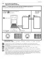
1
2
IS (FISCO) Cl I,II,III Div 1,
Groups A,B,C,D,E,F,G
3
Axiom Enclosure
Quick Connector Pin-out
indicated below (if used)
6
FISCO Approved
Control Equipment
AMI93 Terminal
Identifiers
FB +
FB -
FISCO Approved
Fieldbus Device “n”
FISCO Approved
Fieldbus Device #2
FISCO
Approved
Termination
4
5
OUT 2 - (3)
SIM JMPR (1)
SIM JMPR (2)
OUT 2 + (4)
FB - (7)
OUT 1 - (5)
OUT 1 + (6)
FB + (8)
PIN
SIGNAL
1
FB-
2
FB+
3
Not Used
4
Not Used
PIN
SIGNAL
1
FB-
2
FB+
3
Not Used
4
Not Used
4-PIN MICRO-CONNECTOR
MALE (PINS)
4
3
2
1
4-PIN MINI-CONNECTOR
MALE (PINS)
1
4
3
2