


2
7 AMI 70 en
READ THESE INSTRUCTIONS FIRST!
These instructions provide information about safe handling and operation of the on/off valve controller.
If you require additional assistance, please contact the manufacturer or manufacturer's representative.
Addresses and phone numbers are printed on the back cover.
SAVE THESE INSTRUCTIONS!
Subject to change without notice.
All trademarks are property of their respective owners.
Table of Contents
1
GENERAL........................................................ 3
1.1
Introduction ............................................ 3
1.2
Markings ................................................ 3
1.3
Specifications......................................... 3
1.4
CE marking ............................................ 5
1.5
Recycling and disposal ......................... 5
1.6
Safety precautions ................................. 5
2
ASSEMBLY AND MOUNTING ........................ 5
3
SENSING AND COMMUNICATIONS MODULE
SENSOR SETTING.......................................... 6
3.1
Bench testing ......................................... 6
3.2
Fault alerts for AMI96_D......................... 7
3.3
Additional features for AMI96_D ............ 8
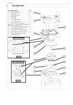
4
EXPLODED VIEW ........................................... 9
5
DIMENSIONS................................................. 10
6
WIRING DIAGRAMS ..................................... 11
6.1
Type AMI33.......................................... 11
6.2
Type AMI44.......................................... 11
6.3
Type AMI96.......................................... 12
6.4
Type AMI96_D ..................................... 12
6.5
Type AMI97.......................................... 12
6.6
Type AMI93.......................................... 13
6.7
Type AMI94.......................................... 13
6.8
Installation Diagram for Explosive
Atmospheres for Europe ...................... 14
6.9
Intrinsic Safety Hazardous Location
Installation Diagram ............................. 15
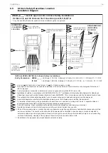
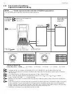
6.10 Non-Incendive Field Wiring Apparatus
Installation Drawing.............................. 16
6.11 Non-Incendive Safety Hazardous
Location Installation Diagram .............. 17
6.12 Intrinsic Field Wiring Apparatus
Installation Drawing.............................. 18
7
TYPE CODE................................................... 19