


kajaaniMCA
i – Installation, Operating & Service
- A5.5 -
W4610201 V2.5 EN
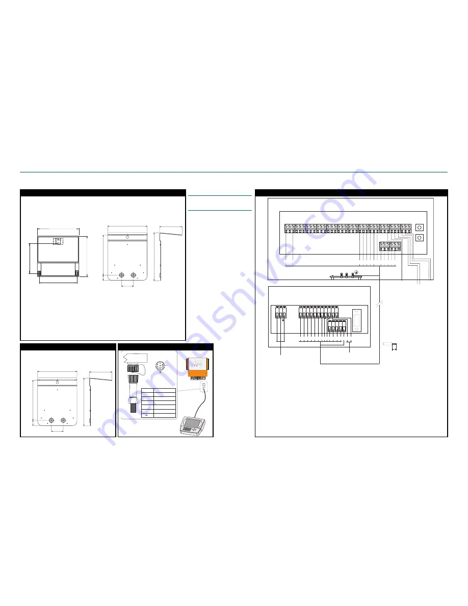
Installation and connections of MCAi sensor
1 3 3
( 5 1 5 / 6 4 " )
2 3 2
( 9 1 1 / 6 4 " )
3 1
( 7 / 3 2 " )
7 0
( 3 / 4 " )
282
(11 3/
32"
)
236
(9
19/
64"
)
1 6 6
( 6 1 7 / 3 2 " )
1 5 1
( 5 1 5 / 1 6 " )
120
(4
23/
32"
)
162
(6
3
/8
")
Installing the Display Unit and its shield
1. Choose an easily accessible location, and mount the shield on the wall with three screws.
2. Watch the distance between Display Unit and sensor – the length of the connection cable is
10m (33 ft).
3. Fasten the Display Unit to the shield with three screws. First hang the unit to the topmost
screw, and then attach the screws in the lower corners.
Installing the Communicator-i shield
1 3 3
( 5 1 5 / 6 4 " )
2 3 2
( 9 1 1 / 6 4 " )
3 1
( 7 / 3 2 " )
7 0
( 3 / 4 " )
282
(11 3/
32"
)
236
(9
19/
64"
)
1. If the Communicator (option) will be used, choose
a location close to the Display Unit and mount its
shield on the wall with three screws.
Dimensions of Display Unit
Dimensions of Display Unit shield
Connections of Display Unit:
•
Mains power (90...260 VAC)
•
RS232, PC-connection
•
Communicator-connection
•
HART-connection
•
Cs current signal
Connection between MCAi Field Connection Board and Display Unit
Terminal (Display unit) ........ Term. (MCA
i
) ............. Signal ............................................................... Wire color
1 ....................................... 1 ...................... +24VDC to MCA
i ..............................................
Brown
2 ....................................... 3 ...................... 0 VDC to MCA
i ..................................................
White
3 ....................................... 38 .................... PC-conn. RS232 TX ......................................... Purple
4 ....................................... 37 .................... PC-conn. RS232 RX ......................................... Black
5 ....................................... 39 .................... PC-conn. RS232 GND ...................................... Red
6 ....................................... 41 .................... Aout1– & Hart ................................................... Blue
7 ....................................... 40 .................... Aout1+ & Hart ................................................... Pink
8 ....................................... 22 .................... TDX2A (RS485 RX/TX+ to display ................... Grey
9 ....................................... 23 .................... TDX2B (RS485 TX/TX- to display ..................... Yellow
10 ............................................................... Aout1– (Cs current signal– to DCS)
11 ............................................................... Aout1+ (Cs current to DCS)
12 ..................................... 26 .................... TDX1A (RS485 TX+ to Communicator-i) .......... Green
13 ..................................... 27 .................... TDX1B (RS485 TX- to Communicator-i) ........... Brown-green
14 ..................................... 24 .................... TDX1B (RS485 RX+ to Communicator-i) ......... White-green
15 ..................................... 25 .................... TDX1B (RS485 RX- to Communicator-i) .......... Red-blue
16 ..................................... Ground bar ...... Prot. GND ......................................................... Yellow-green
1
2
3
4
5
6
D i s p l a y
U n i t
P i n 1 + 2 4 V
P i n 2 G N D
P i n 3 R S - 4 2 2
P i n 4 R S - 4 2 2
P i n 5 R S - 4 2 2
P i n 6 R S - 4 2 2
c a b l e s h i e l d
H A R T
R E S U L T
S A M P L E
I N F O
D I A G
M E A S
R
C S = 3 . 0 8 %
Connecting a Communicator-i to Display Unit
Electric connections
NOTE: Before connecting the mains
power wires, make sure that the wires
are not powered!
1. Insert the Display Unit cable to the
Field Connection Board through
the cable inlet bushings. Connect
the wires as shown on the right.
2. Connect the necessary current sig-
nal cables to the analog outputs.
Consistency signal – connect ei-
ther to the Display Unit or to the
sensor’s Field Connection Board
(not both).
3. Connect the alarm output (open-
ing contact: terminals 17 & 18,
closing contact: 18 & 19).
4. Ground the cable between sensor
and Display Unit by connecting
the cable shield to the sensor elec-
tronics’ ground bar. Ground the
current output and alarm output
cables at only one end (not both).
5. Connect operating voltage (90...
260V) to the terminal on the left
side of Display Unit.
6. Connect a Communicator-i or
HART communicator (if used)
to the unit.
2 4 V D C
I N P U T
+
+
-
-
BI
N
1+
BI
N
1-
BI
N
2+
BI
N
2-
BI
N
3+
BI
N
3-
BI
N
4+
BI
N
4-
AI
N
1+
AI
N
2+
AI
N
2-
AL
AR
M
1
AL
AR
M
2
AL
AR
M
3
RX
D2
A
RX
D2
B
TX
D
2A
TX
D
2B
RX
D1
A
RX
D1
B
TX
D
1A
TX
D
1B
2 4 V D C
O U T
+
-
AO
U
T1
+
AO
U
T1
-
AO
U
T2
+
AO
U
T2
-
AO
U
T3
+
AO
U
T3
-
R E S E T
A B O R T
AI
N
1-
1
2
3
4
5
6
7
8
9
1 0
1 1
1 2
1 3
1 4
1 5
1 6
1 7
1 8
1 9
2 0
2 1
2 2
2 3
2 4
2 5
2 6
2 7
2 8
2 9
3 0
3 1
3 2
3 3
3 4
3 5
3 6
R S - 2 3 2
3 7
3 8
3 9
4 0
4 1
4 2
H A R T
1 2 3 4 5 6 7 8 9 1 0 1 1
1 2 1 3 1 4 1 5 1 6
R S - 2 3 2
0
~
90...260 VAC
1
3
2 2 2 3 2 4 2 5 2 6 2 7 3 7 3 8 3 9 4 0 4 1
1
2
1 4 1 5
9
1 3
1 2
3
4
7 8
5
6
5 - 6 m m
+
-
1 6
Display Unit
Field Connection Board
Sensor connections:
•
3 current outputs (consisten-
cy, temperature, chemicals
content)
•
Alarm output
•
4 binary inputs
•
2 analog inputs
Cs current output
(or from Field Conn. Board)
Temp. or
Chem.content
current output
Cs current output
(or from Display Unit)
Chem. content
or Temp.
current output
Summary of Contents for kajaaniMCAi
Page 1: ...kajaaniMCAi Installation operating service manual W4610201 V2 5 EN for software version 2 5 ...
Page 59: ...kajaaniMCAi Installation Operating Service A1 W4610201 V2 5 EN App 1 Technical specifications ...
Page 61: ...kajaaniMCAi Installation Operating Service A2 W4610201 V2 5 EN App 2 Contents of delivery ...
Page 66: ...kajaaniMCAi Installation Operating Service A4 W4610201 V2 5 EN App 4 Spare parts ...
Page 68: ...kajaaniMCAi Installation Operating Service A5 W4610201 V2 5 EN App 5 Installation instruction ...


