


kajaaniMCA
i – Installation, Operating & Service
- 7.2 -
W4610201 V2.5 EN
F 7
F 6
F 5
F 4
F 8
F 3
F 1
F 2
F 9
F 1 0
F 1 1
F 1 2
F 1 3
F 1 4
F 1 5
F 1 6
i
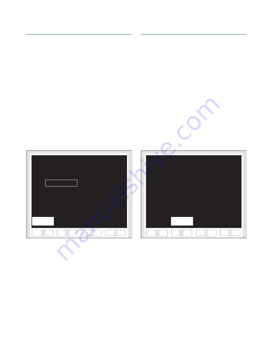
CALIBRATION IN USE
17.10.00 13:57
Temp = 68.5 °C
MCA = 3.24 %
Lab =
3.35 %
Average filler content =
0.0 %
from which
Kaolin = 25.0 % Talc = 25.0 %
CaCO3 = 25.0 % TiO2 = 25.0 %
Edit
Fig. 7.3. “Calibration in use” display.
7.B. Modifying the Calibration
If calibration remains inaccurate for some reason, a
constant level difference will be observed between the
measured consistency and the laboratory analysis re-
sult. This level difference can be corrected without
repeating the sampling process, using the “Calibration
in use” display (Fig. 7.3).
Example: if the MCAi steadily shows about 0.2%
higher consistency than laboratory, correct as follows:
1. Go from M
AIN
M
ENU
=> E
NTER
LAB
=> C
ALIBR
.
IN
USE
. The previous completed calibration will appear
on the screen.
2. Press [F1&F2] E
DIT
, and enter a value that is 0.2%
lower than the currently set “Lab” value (i.e. “Lab”
= 3.15%).
3. Press [F3&F4] S
AVE
to save the changes.
4. Press [F5&F6] Y
ES
to change the calibration.
When modifying the calibration, also the average filler
content can be changed; this is necessary if the filler
content values have changed by more than 5%.
7.C. Calibration and Sample History
All samplings and changes to calibration are stored as
history data in the memory. The data can be scrolled
using the following displays.
7.C.1. Calibration history
Go from M
AIN
M
ENU
=> E
NTER
LAB
=> C
ALIBR
.
HISTORY
(Fig. 7.4).
This display lists the performed calibrations, ar-
ranged according to date. The display also shows the
following data:
•
Sample: date when the calibration sample was
taken.
•
Temp °C: temperature in the process.
•
MCAi %: measured process consistency.
•
Lab %: laboratory consistency used in calibration.
•
Fil %: filler content value used in calibration.
Use keys [F3&F4] P
AGE
BACKWARDS
and [F1&F2]
P
AGE
FORWARDS
to scroll the history table back and forth.
F 7
F 6
F 5
F 4
F 8
F 3
F 1
F 2
F 9
F 1 0
F 1 1
F 1 2
F 1 3
F 1 4
F 1 5
F 1 6
i
CALIBRATION HISTORY
Date
Sample Temp MCAi Lab Fill
°C % % %
18.10.00 18.10.00 69.7 3.38 3.15 0
18.10.00 17.10.00 68.5 3.17 3.15 0
17.10.00 17.10.00 68.7 3.30 3.15 0
Page
backwards
Fig. 7.4. “Calibration history” display.
Summary of Contents for kajaaniMCAi
Page 1: ...kajaaniMCAi Installation operating service manual W4610201 V2 5 EN for software version 2 5 ...
Page 59: ...kajaaniMCAi Installation Operating Service A1 W4610201 V2 5 EN App 1 Technical specifications ...
Page 61: ...kajaaniMCAi Installation Operating Service A2 W4610201 V2 5 EN App 2 Contents of delivery ...
Page 66: ...kajaaniMCAi Installation Operating Service A4 W4610201 V2 5 EN App 4 Spare parts ...
Page 68: ...kajaaniMCAi Installation Operating Service A5 W4610201 V2 5 EN App 5 Installation instruction ...


