


CHIMNEY ENVIRONMENT
It is suggested that a chimney being installed in a corrosive
atmosphere be constructed of Type 316 stainless steel.
Type 316 stainless is resistant to corrosion and will add to
the life expectancy of the installation. Chemicals containing
halogen compounds should not be allowed to contaminate the
combustion air supplied to the heating equipment. Storage or
use of chemicals containing chlorine or chlorides in the vicinity
of equipment, or the presence of these compounds in the fuel,
or combustion air supply may lead to early deterioration of the
chimney.
Chemicals which may cause attack on chimney materials include
(but are not limited to):
•
chlorinated or halogenated dry cleaning solutions,
•
fluorocarbon refrigerants,
•
hydrochloric (muriatic), sulfuric or other acids,
•
fluorocarbon aerosol propellants,
•
vinyl plastics (when burned),
•
chlorine bleach and cleaning solutions,
•
titanium tetrachloride, or
•
plating or etching baths or solutions.
Any of these chemicals passing through the combustion process
produce acids which can corrode the heating equipment and the
chimney.
If corrosion is found, an immediate investigation should be
undertaken of the entire area. Any corrosive materials should
be removed to avoid future contamination. A contaminate-free
atmosphere for combustion and ventilation air must be obtained.
It may be necessary to pressurize the equipment room with its
own air supply. Any surface discoloration should be carefully
studied as it may be caused by contaminates in the fuel, or
corrosion of mild steel components of the chimney system, the
breeching system, or the equipment being vented and may be
indicative of deterioration of other components of the heating
system.
Whenever the local atmosphere is high in pollutants, constantly
or intermittently, it is recommended that the chimney components
be of all stainless steel construction. When chimney is exposed
to the elements, it is recommended that the outer wall be
either painted with one base coat and one finish coat of a heat
resistant primer and paint, or that the outer wall be constructed
of stainless steel.
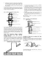
TERMINATION HEIGHT REQUIREMENTS
Model PIC/IPIC chimney is to terminate a minimum of 3’ (914)
above the highest point where it passes thru a roof of a building
and a minimum of 2’ (610) higher than any portion of a building
within a horizontal distance of 10’ (3.05m) (See
FIG. 1
).
CLEARANCES – BOILERS AND ENGINES
CAUTION– DO NOT ENCLOSE IN A CHASE OR PASSAGEWAY
OF COMBUSTIBLE MATERIAL
For appliances operating with continuous exhaust temperatures
up to 1400º F, where the chimney is installed in an open room
or fully ventilated area on the same story as the appliance to
which it is connected, Model PIC/IPIC Chimney shall be installed
at a minimum of the clearance to combustibles as indicated in
TABLE 1
.
Except for installation in one or two family dwellings, a factory-
built chimney that extends through any zone above that on which
the connected appliance is located is to be provided with an
enclosure having a fire resistance rating equal to or greater than
that of the floor or roof assemblies through which it passes.
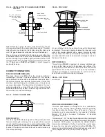
Metal-Fab Model PIC/IPIC Chimney can penetrate a combustible
roof by utilizing the Roof Support Assembly (RSA) or Ventilated
Thimble Assembly (VTA). All other parts are for attachment to
non-combustible construction (i.e., floor guides, wall guides,
plate or wall support assemblies).
TABLE 1 - PIC/IPIC INSTALLATION CLEARANCES
Operating Temperature
1000°F Continuous
(538°C)
1400°F Intermittent
(760°C)
1400°F Continuous
(760°C)
1800°F Intermittent
(982°C)
Insulation
Thickness
PIC
IPIC-1 IPIC-2
IPIC-4
PIC
IPIC-1
IPIC-2
IPIC-4
Exterior Wood Frame or Combustible Wall
Diameter: 6”
8 - 16”
18”
20”
22”
24 - 26”
28 - 32”
34”
36 - 40”
42 - 48”
4” (102)
4” (102)
5” (127)
6” (152)
6” (152)
6” (152)
6” (152)
6” (152)
6” (152)
6” (152)
1” (25)
2” (51)
3” (76)
3” (76)
3” (76)
3” (76)
4” (102)
5” (127)
5” (127)
6” (152)
1” (25)
1” (25)
1” (25)
1” (25)
1” (25)
1” (25)
1” (25)
1” (25)
1” (25)
1” (25)
4” (102)
4” (102)
6” (152)
8” (204)
9” (229)
10” (254)
10” (254)
10” (254)
10” (254)
10” (254)
1” (25)
2” (51)
3” (76)
3” (76)
3” (76)
3” (76)
4” (102)
5” (127)
5” (127)
6” (152)
1” (25)
1” (25)
1” (25)
1” (25)
1” (25)
1” (25)
1” (25)
1” (25)
1” (25)
1” (25)
Exterior Non-Combustible
Diameter: 6”
8 - 18”
20 - 42”
44 - 48”
2” (51)
2” (51)
4” (102)
4” (102)
1” (25)
2” (51)
3” (76)
4” (102)
1” (25)
1” (25)
1” (25)
1” (25)
2” (51)
2” (51)
4” (102)
4” (102)
1” (25)
2” (51)
3” (76)
4” (102)
1” (25)
1” (25)
1” (25)
1” (25)
Interior Wood or Other Combustibles
Diameter: 6”
8 - 16”
18”
20”
22”
24”
26”
28 - 32”
34”
36 - 40”
42 - 48”
4” (102)
4” (102)
5” (127)
6” (152)
7” (178)
8” (204)
9” (229)
10” (254)
10” (254)
10” (254)
10” (254)
1” (25)
2” (51)
3” (76)
3” (76)
3” (76)
3” (76)
3” (76)
4” (102)
5” (127)
5” (127)
6” (152)
1” (25)
1” (25)
1” (25)
1” (25)
1” (25)
1” (25)
1” (25)
1” (25)
1” (25)
3” (76)
3” (76)
4” (102)
4” (102)
6” (152)
8” (204)
9” (229)
10” (254)
10” (254)
10” (254)
10” (254)
10” (254)
10” (254)
1” (25)
2” (51)
3” (76)
3” (76)
3” (76)
3” (76)
3” (76)
4” (102)
5” (127)
5” (127)
6” (152)
1” (25)
1” (25)
1” (25)
1” (25)
1” (25)
1” (25)
1” (25)
1” (25)
1” (25)
3” (76)
3” (76)
Fully Enclosed Combustibles (UL103-HT)
Diameter: 6”-14”
N/A
N/A
2” (51)
N/A
N/A
N/A
Fire Rated or
Non-Combustible
Chase
As necessary for installation and access, refer to NFPA 211.
Note: The above figures represent air space, in inches, from
outer surface to surroundings.
NOTES:
1. False ceilings are a potential hazard and require
firestopping. Chimneys passing through areas between
ceiling and roof must be installed in fire-rated
enclosures in accordance with local building codes.
2. Decorative shrouds at the termination of a factory built
chimney shall not be permitted per NFPA 211.
2’ (610)
LESS THAN
10’ (3048)
MORE THAN 10’ (3048)
3’ MIN. (914)
STRUCTURE
CHIMNEY OR VENT
3
FIG. 1 - TERMINATION HEIGHT REQUIREMENTS