


RELIEF VALVE (RV)
The relief valve is intended for use with diesel engines to
provide extra protection to the pipe in case of a delayed ignition
of unburned fuel in the exhaust system. It consists of a spring
loaded disk valve mounted on a flange adapter. The valve is
factory calibrated to open at 27 in. wc. The calibration nuts must
not be changed or the valve may not function correctly.
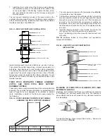
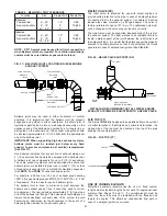
The relief valve must be supported independently of the rest of
the exhaust system. The best method to accomplish this is to
locate a plate support at the joint between the relief valve and
the adjacent fitting. It is crucial that the plate support be properly
secured to building structure so that it can withstand the forces
generated in case of delayed fuel ignition (See
FIG. 58
).
METAL-FAB RECOMMENDS THAT ALL DIESEL ENGINE
EXHAUST SYSTEMS BE EQUIPPED WITH A RELIEF VALVE.
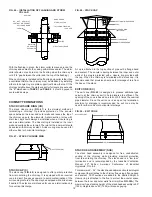
FLIP TOP (FT)
The flip top (
FIG. 59
) is designed to be installed either on a vertical
or horizontal exhaust. If installed on a horizontal termination, the
hinged side of the top must be oriented at the top of the pipe
keeping the counterweight up.
FIG. 58 – RELIEF VALVE SUPPORT (RV)
TO MUFFLER
TO VENT
RELIEF
VALVE
PLATE SUPPORT
(SECURE TO BUIDING)
FIG. 59 – FLIP TOP (FT)
FLIP TOP
CLOSURE RING
21
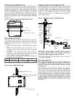
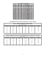
TABLE 9 - BELLOWS JOINT CLEARANCE
Location
Size
Single Wall
Double Wall
Exterior
Combustible
Non-combustible
6” - 48”
6” - 18”
20” - 48”
18”
2”
4”
SEE
TABLE
1
Interior
Combustible
Non-combustible
6” - 48”
6” - 18”
20” - 48”
18”
2”
4”
SEE
TABLE
1
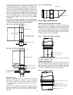
FIG. 57 – BELLOWS JOINT LOCATION IN DIESEL ENGINE
EXHAUST SYSTEM
Bellows joints may be used in either horizontal or vertical
positions. It is imperative that the bellows joint be properly
supported and guided in either orientation. A bellows joint is
typically supported by a plate or wall support assembly on the
appliance end of the bellows and guided by a full angle ring or
wall guide on the exhaust end. The exhaust side guide should
be located approximately 6”-12” (152-305) from the downstream
end of the bellows joint.
IMPORTANT: When supporting high rise exhaust systems,
bellows joints must be located just below every fixed
support to prevent compression at ambient temperatures
(See FIG. 57).
Good design indicates that any section of exhaust piping over
4’ (1.2m) between fixed points be equipped with a bellows joint.
A bellows joint can compensate for up to 3” (76) of expansion.
The entire exhaust system should be examined to assure that
bellows joints are installed in pipe runs in which 3” (76) or less
of expansion is expected. For a method of calculating expansion
(See
NOTE 3 on PAGE 11
under expansion joints).
For example, a 60-foot run (18.3m) of exhaust pipe handling
1000º F flue gas would produce 60ft/100 X 1000ºF/100 = 6” (152)
of expansion. This run would require 2 bellows joints.
The bellows joint is lined to minimize contact between the
bellows and exhaust gases. Thus, it cannot be used to correct
mis-alignment. The liner extends approximately 2” (51) past one
end of the bellows joint flange. This extension should always be
toward the downstream (exhaust) side of the system to avoid
becoming an obstruction for the shockwave in the event of a
delayed ignition incident in the exhaust system.
3” (76) EXPANSION
MAXIMUM
HALF ANGLE
LINER
TOWARD VENT
APPLIANCE OUTLET
BELLOWS
JOINT
BELLOWS
JOINT
PLATE SUPPORT
PLATE SUPPORT
USE OF VARIABLE LENGTH
Metal-Fab generally recommends the use of fixed custom
lengths where standard lengths do not work for engine exhaust
systems (See Pages 10 and 11). If a variable length must be
used, the inner tube must be installed with the flanged end
toward the engine. This allows an unobstructed flow path in
case of a delayed ignition occurrence.
NOTE: P071 Sealant must be used for all joint connections
when Bellows Joints are required. For exterior installations,
sealant must be cured before exposure to moisture.