


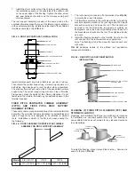
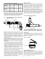


The proper location for a wall guide is immediately below the
outer closure band near a pipe joint. The outer band must be
able to move away from the wall guide when thermal expansion
occurs (See
FIG. 36
).
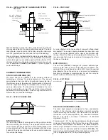
SPECIAL CONSIDERATIONS
When a wall support assembly is used to support a chimney on
an exterior wall, wind loading must also be considered. Below the
highest wall support assembly, the chimney must be resupported
at intervals not greater than 40’ (12.19m) (See
TABLE 5
). The
chimney must be equipped with wall guides between each wall
support assembly. Guide spacing is in accordance with maximum
vertical spacing in
TABLE 6
on Page 5. Additionally, a wall guide
must be located between 6’ and 10’ (1.83m and 3.05m) below the
highest wall support to stabilize the freestanding portion of the
chimney above the wall support assembly (See
FIG. 37
).
FIG. 37 – SPECIAL CONSIDERATIONS FOR CHIMNEY ON
OUTSIDE WALL
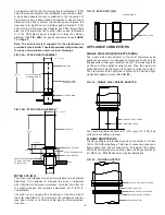
FLOOR GUIDE (FG)
The floor guide is similar in function to a wall guide or full angle
ring, but is modified specially for use at floor penetrations. The
angle brackets and straps hold the guide centered in the floor
penetration (See
FIG. 38
). Maximum floor opening “X” is Duct
I.D. + 10” (254).
FIG. 38 – FLOOR GUIDE
FREE STANDING
6 TO 10 FEET
(1829 -3048)
WALL GUIDE
LOCATE EXPANSION JOINT
OR BELLOWS JOINT BELOW
WALL GUIDE
WALL SUPPORT
DO NOT INSTALL AN
EXPANSION JOINT IN
THIS AREA DUE TO
BENDING FORCES
38” THRU 48” PIC ONLY
15
STRAPS
ANGLE
BRACKET
FLOOR
ANGLE
RING
“X”
“X”
DO NOT ATTACH THE FLOOR GUIDE TO
COMBUSTIBLE CONSTRUCTION.
FIG. 36 – WALL GUIDE LOCATIONS
6”-12” (152-305)
PIPE FLANGES
WALL GUIDE OR
FULL ANGLE RING
(STRUCTURE BY
OTHERS)
PIPE
DO NOT ATTACH THE WALL GUIDE TO
COMBUSTIBLE CONSTRUCTION.
FIG. 35 – WALL GUIDE ASSEMBLED VIEW