


NOTES:
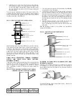
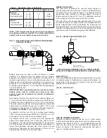
1. It is recommended that the pipe adjacent to the variable
length is supported or guided to prevent sagging.
2. If a variable length must be installed adjacent to a tee,
elbow, wye or other fitting where tube can interfere with
flow, the unflanged end of the tube should be away from
the fitting and fitted into a pipe length in the manner
described in the installation procedure under FIG. 23.
3. A variable length may be installed with a flange to flange
length between 4” and 26” (102 and 660) inclusive.
4. If inner tube is too long, it may be cut to length. Tube
must be a minimum of 4” (102) longer than flange to
flange length. Prior to installation of cut pipe, remove all
burrs to ensure that interference does not occur.
5. Note that the variable length will not support any weight
in the vertical position.
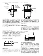
STEP INCREASER (SI) AND TAPERED INCREASER (TI)
Frequently, a diameter change is required in a chimney
installation. To accomplish such a size change, a step increaser
or tapered increaser may be used. These parts are usually used
to provide an increase of size, as the name implies. However,
they may be used to reduce the size of a run. Extreme caution
should be exercised when reducing the size of a chimney. The
resultant pressure drop may cause the chimney to mis-function
and cause spillage of flue gases into the mechanical room.
The step increaser should be used when the length of run
available for the size change is restricted. The installed length of
a step increaser is 2” (51) (See
FIG. 25
). The step increaser is a
non-structural part and must not be subjected to loading in either
the axial or lateral directions.
FIG. 24 – VARIABLE LENGTH CASING ASSEMBLY
Note: For IPIC, wrap increaser with insulation before
attaching outer casing. Care must be taken to completely fill
all gaps with insulation.
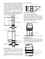
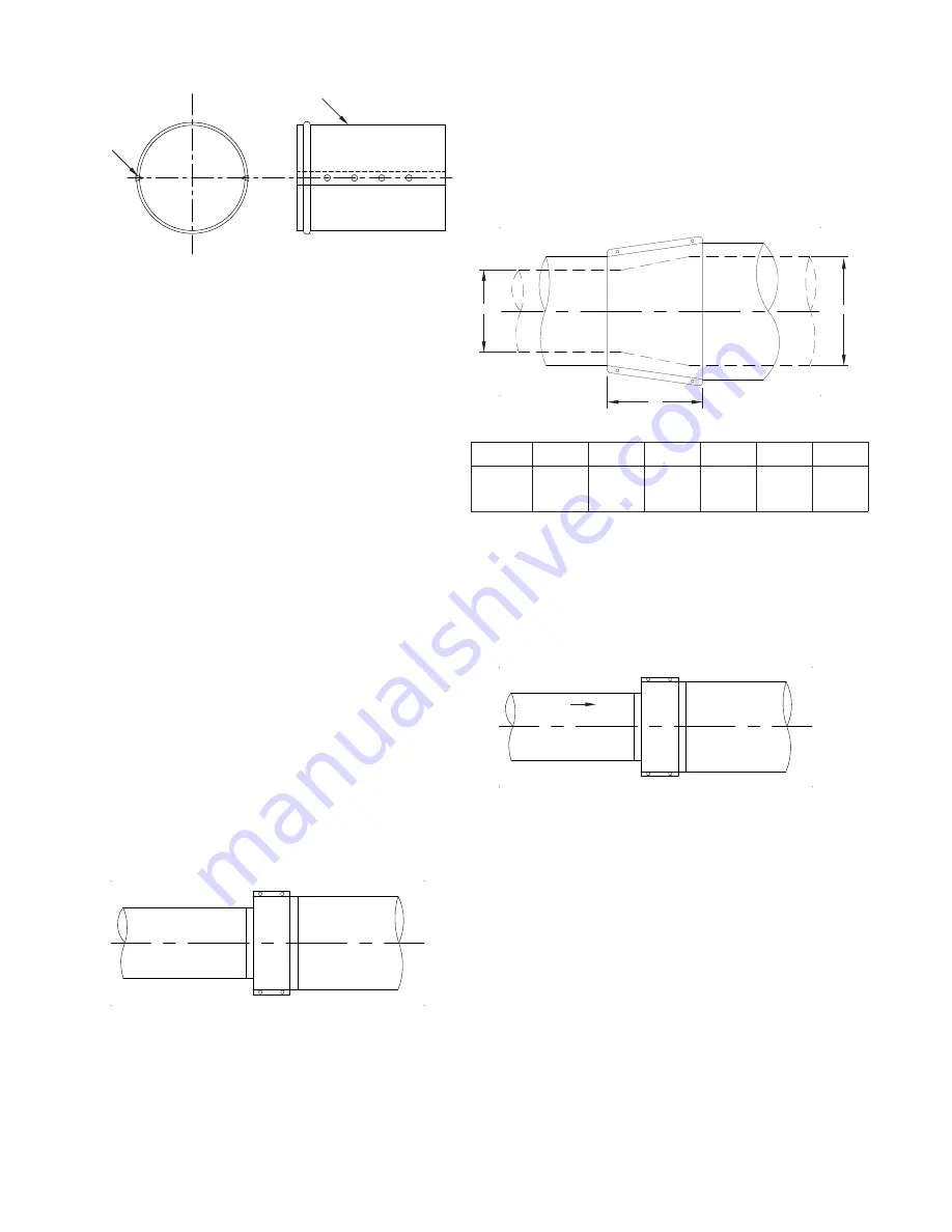
When sufficient length is available, use of a tapered increaser
is recommended, since it causes a considerably less pressure
drop than an equivalent step increaser. The tapered increaser
uses 5 inches of length per incremental diameter change. The
maximum length for a tapered increaser is 30” (762) or 6 pipe
sizes. A tapered increaser is considered to have the same load
strength as straight pipe (See
FIG. 26
).
STEPS
1
2
3
4
5
6
“C” =
5”
(127)
10”
(254)
15”
(381)
20”
(508)
25”
(635)
30”
(762)
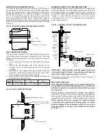
TRANSITION BAND (TB)
The transition band provides the necessary increase or decrease
in casing diameter when change in insulation thickness occurs
(
FIG. 27
).
FIG. 26 - TAPERED INCREASER (TI)
FIG. 27 - TRANSITION BAND (TB)
Note: Wrap pipe joint with insulation before attaching outer
casing. Care must be taken to completely fill all gaps with
insulation.
HALF JACKET
SCREWS
(INCLUDED)
FIG. 25 - STEP INCREASER (SI)
INSTALLS AT 2” (51)
“A”
“B”
“C”
AIR FLOW
12