background image

19

ENGLISH

Information on the nameplate: 

3.4

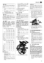
Safety devices

Retractable blade guard

The retractable blade guard 

(29)

 pro-

tects against unintentional contact with
the saw blade and from chips flying
about.

Both segments of the retractable blade
guard must always return automatically
into their starting position: when the saw-
head is lifted up, the sawblade must be
covered all around. 

Safety lock

The safety lock 

(30)

 prevents the retract-

able blade guard from unintentional
opening. 


For cutting the safety lock is pushed to
the side (arrow). Only then can the saw-
head be lowered, opening the retracta-
ble blade guard.
After the cut is made - and the sawhead
is in its upper starting position - the
retractable blade guard is locked again
by the safety lock. 

A

Caution!


Do not carry tool at the handle;

the handle is not designed to bear the
weight of the tool. To carry, hold the
tool at both sides of the base. 

Installation 

1.

Lift the tool out of the box with the
help of another person.

3

Note:

If the machine is set up on the

workstand:

do not

 install the rubber feet! 

2.

To install the rubber feet tilt the
machine: 

The rubber feet must be accessi-
ble from both sides.

The machine must rest firmly in
its tilted position. 

3.

Put nu

(34)

 into the hole on the

underside of the rubber foot. 

4.

Put hexagon socket screw 

(31)

 from

the top through the machine's foot.
Put a washer 

(32)

 on the screw and

screw the rubber foot 

(33)

 with the

fitted nut 

(34)

 on.

5.

Tighten rubber foot hand-tight only.
To do so, hold the screw with the
Allen key to counter. 

6.

Tighten the screw with the Allen key
hand-tight. 

7.

Place tool on a suitable base:

All four feet must firmly rest on
the base. 

The ideal height of the base is
800 mm. 

The saw must stand securely,
even when cutting larger work-
pieces. 

8.

Push the sawhead slightly down and
pull the transport locking pin 

(35)

 out

– the sawhead can then be fully
lifted. 

Transportation

1.

If necessary, adjust the cutting
depth limiter 

(36)

 to the maximum

depth of cut. 

2.

Lower the sawhead and push the
transport locking pin 

(35)

 in

3.

Keep the packing for future use, or
separate by material and dispose of
in an environmentally friendly man-
ner. 

96

°

 cutting angle range for bevel

cuts (48

°

 left thru 48

°

 right) with five

positive stops. 

(22)

Manufacturer 

(23)

Serial number 

(24)

Machine designation 

(25)

Motor specifications (see also 
"Technical specifications") 

(26)

Year of make 

(27)

CE-mark – This machine con-
forms to the EC directives as per 
Declaration of Conformity 

(28)

Dimensions of permissible saw 
blades 

23

24

25

26

27

28

22

29

4.

Installation and transport

30

5.

Special product features

31

32

33

34

35

36

Summary of Contents for KGS 303

Page 1: ...115 168 6660 3003 1 2 KGS 303 Betriebsanleitung 3 Operating Instruction 16 Instructions d utilisation 28 Manuale d istruzioni 41 A0246IVZ fm ...

Page 2: ...de que este produto está de acordo com as seguintes normas de acordo com as directrizes dos regulamentos Vi försäkrar på eget ansvar att denna produkt överensstämmer med följande standarder enligt bestämmelserna i direktiven FIN SUOMI NO NORGE VAATIMUKSENMUKAISUUSVAKUUTUS SAMSVARSERKLÆRING Vakuutamme että tämä tuote vastaa seuraavia normeja on direktiivien määräysten mukainen Vi erklærer under ege...

Page 3: ...sport locking pin 8 Cutting depth limiter 9 Sawhead tilt locking lever 10 Hinged fence 11 Rotating table 12 Table insert 13 Rotating table locking screw 14 Saw base 15 Fence 16 Retractable blade guard 17 Saw blade lock 18 Safety lock 19 Sawhead 20 Dust spout adaptor for connection of dust collector Tools 21 Allen key 6 mm Machine documents Operating instructions Spare parts list XA0040E2 fm Operat...

Page 4: ...mbered Instructions which can be carried out in any sequence are indicated by a bullet Listings are indicated by an En Dash 3 1 Specified conditions of use This saw is intended for cross cuts bevel cuts mitre cuts and compound mitre cuts of strips profiled ledges etc Grooving is also possible as well Only such materials suitable for cutting by the saw blade fitted may be cut see Tech nical specifi...

Page 5: ...of the above are attached A Hazard generated by insuffi cient personal protection gear Wear hearing protection Wear safety glasses Wear dust mask Wear suitable work clothes Wear non slip shoes A Risk of injury by inhaled wood dust Dust of certain timber species e g beech oak ash can cause cancer when inhaled Work only with a suit able dust collector attached to the saw The dust collector must comp...

Page 6: ...ts tilted position 3 Put nut 34 into the hole on the underside of the rubber foot 4 Put hexagon socket screw 31 from the top through the machine s foot Put a washer 32 on the screw and screw the rubber foot 33 with the fitted nut 34 on 5 Tighten rubber foot hand tight only To do so hold the screw with the Allen key to counter 6 Tighten the screw with the Allen key hand tight 7 Place tool on a suit...

Page 7: ...ocking screw 39 can be turned by 50 to the left and 60 to the right The rotating table engages at positive stops at the 0 15 22 5 30 45 and 60 position A Caution In order to prevent the mitre angle from changing during cutting the rotating table s locking screw must be tightened also when engaged at the positive stops Push pull action The track arm permits the cutting of workpieces having a larger...

Page 8: ...er supply cable so it does not interfere with the work and is not damaged Protect power supply cable from heat aggressive liquids and sharp edges Use only rubber jacketed exten sion cables of sufficient lead cross section 3 x 1 5 mm2 Do not pull on power supply cable to unplug A Danger Before starting any work check to see that the safety devices are in proper working order Use personal protection...

Page 9: ... the rotating table 46 2 Set to desired angle 3 Note The rotating table engages at positive stops at the 0 15 22 5 30 45 and 60 position 3 Tighten the rotating table s locking screw 4 Cut workpiece as detailed under Standard cross cuts 8 3 Bevel cuts 3 Note A bevel cut cuts the workpiece at an angle other than 90 against its sur face Maximum workpiece cross section dimensions in mm Starting positi...

Page 10: ...ng with locking nut 2 Hold workpiece against the fence 3 Note For the groove to be cut at the desired depth across the whole work piece width a suitable spacer strip needs to be placed between workpiece and fence 3 Push the safety lock to the side and press and hold the ON OFF switch 4 Slowly swing the sawhead fully down holding the handle firmly When sawing exert only moderate pressure to prevent...

Page 11: ...peration 8 Put outer blade flange 52 on the two flanks must fit over the flats of the saw spindle 9 Screw on the arbor bolt 51 left handed thread and tighten with the Allen key fingertight To arrest the saw blade use the saw blade lock 50 A Danger Do not extend arbor bolt tighten ing wrench Do not tighten arbor bolt by hit ting the assembly wrench 10 Check function To do so lower the sawhead The r...

Page 12: ... Note The track arm holder engages at positive stops at the 0 22 5 and 45 position 9 5 Machine cleaning Remove chips and saw dust with brush or vacuum cleaner from setting devices operating elements motor vent slots space below table insert 9 6 Machine storage A Danger Store the saw in such way that it can not be started by unauthor ized persons Make sure that nobody can get injured by the stored ...

Page 13: ...hese instructions are printed on paper produced with elemental chlorine free bleaching process In this section problems and faults are described which you may remove your self If the measures detailed here do not solve the problem see under Repairs A Danger Many accidents happen partic ularly in connection with problems and faults Therefore please note Always unplug before servicing Check that all...

Page 14: ...0 20 43 5 550 740 20 This machine is specially designed for the high momentary loads of crosscutting The motor reaches the stated power of 1800 watts at S6 20 5 min intermittent periodic duty type with starting This means that this saw can be operated for 1 minute at full load rating 1800 watts within a 5 minute operating period The motor has to deliver these 1800 watts only under extreme load con...

Page 15: ...091 005 7553 D 091 005 7537 E 091 005 7545 F 091 005 7529 G 091 003 0973 H 091 003 1058 I 091 003 0981 J 091 003 1040 HW 250 x 2 8 2 0 x 30 24 W HW 250 x 2 4 1 8 x 30 48 W HW 250 x 2 4 1 8 x 30 60 W HW 250 x 2 8 2 0 x 30 80 TF U3a0246 fm ...

Reviews: