


and
SQA-V
Service Manual Dec_2019
31
8.
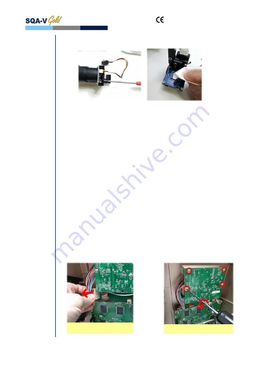
Remove the dust sleeve by unscrewing 2 Phillips screws (fig. 10).
9.
Gently clean the CCD using lint free microfiber cloth (fig. 11).
10.
Attach the dust sleeve back to the CCD board and fasten 2 Phillips screws through
designated holes in CCD tray
11.
Carefully align the false track tool with the metal guide rail and gently push the CCD
tray back over the guide rail.
12.
Re-install the black stopper to the bench and fasten the screws.
13.
Re-connect the internal and external video cables.
14.
Assemble the lid on the base of visualization system and fasten the screws.
15.
Assemble the DC motor, and make sure the cogwheel teeth coincide with the teeth of
the white plastic rack.
16.
Re-attach the visualization system back to the front panel.
Instructions
for all range
of SQA-V’s
serial
numbers
17.
Replacing the CCD camera (no image on both SQA-V and V-sperm)
1.
Follow the instructions for CCD cleaning, but this time do not remove the dust sleeve.
2.
Using a Phillips screwdriver remove the four screws holding the camera PCB.
3.
Replace the defective CCD camera with a new one.
4.
Fasten the four screws holding the CCD camera.
5.
Follow the rest of instructions to finish the assembling of the visualisation system and
re-attach it to the front panel.
Video screen
18.
Video screen (Part# LCD-0010)
ISSUE:
The image on the Video Screen is wavy
Note:
This repair can
only be
performed for
SQA-V of SN
1505 and
above. For
systems with
different serial
numbers,
please contact
MES support
services.
1.
Open the SQA-V device
2.
Disconnect the video screen cable from Control board
3.
Using a Phillips screwdriver, remove the screws holding the PCB of the video screen
4.
Remove the hollow spacers holding the Video screen
5.
Replace the defective video screen with new one
6.
Re-assemble the spacers
7.
Using a Phillips screwdriver, secure the PCB of the video screen with the screws
8.
Connect the video cable of the new video screen
9.
Close the SQA-V
Fig. 10
Fig. 11
Remove the screws
Disconnect the Video screen
cable


