8-49
Processing Components - Limiter
one. The two quantities are then compared and the larger is
returned as the signal level.
When the Crest Factor Sensitivity is set to 0.00 the ISP-100
limiter operates as a traditional limiter responding to average
signal levels; when the Crest Factor Sensitivity is set to 1.00 the
ISP-100 limiter operates as a traditional limiter responding to
peak signal levels. Values in-between represent various hybrids
of the two. If the limiter is to ignore peaks and respond only to
average levels, then the Crest Factor Sensitivity may be set near
zero. If the limiter is to respond only to peaks, then the Crest
Factor Sensitivity may be set near one.
Good results may be obtained by following these steps:
1. Set the Crest Factor Sensitivity to 0.00. This will cause the
ISP-100 limiter to behave like a traditional limiter responding
to average signal levels.
2. Set all of the other limiter controls as appropriate for the
signal being limited, just as they would be set in a traditional
limiter.
3. Adjust the Crest Factor Sensitivity control so that the limiter
responds appropriately to short signal peaks. If it were
possible to know, in advance, what the crest factor of the
input signal was going to be, then the Crest Factor Sensitivity
control would ideally be set to 1/(the crest factor of the input
signal).
Since this quantity is not generally known, it is best to
experiment until satisfactory results are obtained.
Metering
The limiter meter shows the attenuation applied to the signal
passing through the limiter at any given moment in time. When
the signal is being limited the meter indicates negative values
(gain less than 1.0). When the signal is
not being limited the
meter indicates 0 dB (gain of 1.0). Meter values are raw, no
averaging or ballistics are applied.
Notes on Operation of the Limiter:
Bypass
Bypassing a limiter causes the signal to pass through unaltered.
Overshoot
The limiter algorithm used in the ISP-100 allows for a small
amount of overshoot on transients, regardless of the settings of
the Detection Window and Crest Factor Sensitivity controls. The
amount of overshoot is somewhat dependent upon the setting of
the Threshold control; the lower the threshold the greater the
overshoot. This represents normal operation for the limiter.
Summary of Contents for Integrated Signal Processor ISP-100
Page 1: ...User s Manual ISP 100 INTEGRATED SIGNAL PROCESSOR...
Page 2: ...THIS PAGE LEFT BLANK INTENTIONALLY...
Page 24: ...2 10 10 July 1998 THIS PAGE LEFT BLANK INTENTIONALLY...
Page 32: ...3 8 10 July 1998 THIS PAGE LEFT BLANK INTENTIONALLY...
Page 48: ...5 6 10 July 1998 THIS PAGE LEFT BLANK INTENTIONALLY...
Page 126: ...A 4 10 July 1998 THIS PAGE LEFT BLANK INTENTIONALLY...
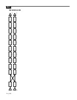
Page 128: ...B 2 10 July 1998 MONDOEQ QMS...
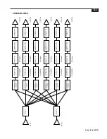
Page 129: ...B 3 Standard QuickMAPs 2X6CMBC QMS...
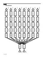
Page 130: ...B 4 10 July 1998 2X8COMB QMS...
Page 131: ...B 5 Standard QuickMAPs 3X6CMBC QMS...
Page 132: ...B 6 10 July 1998 2X8THRU QMS...
Page 133: ...B 7 Standard QuickMAPs 4CHAN QMS...
Page 134: ...B 8 10 July 1998 4X6CMBC QMS...
Page 135: ...B 9 Standard QuickMAPs 4X6THRU QMS...
Page 136: ...B 10 10 July 1998 3_2W QMS...
Page 137: ...B 11 Standard QuickMAPs 2WAYS QMS...
Page 138: ...B 12 10 July 1998 2_3WAY QMS...
Page 139: ...B 13 Standard QuickMAPs 2_2W_SUB QMS...
Page 140: ...B 14 10 July 1998 2_2W_FR QMS...
Page 141: ...B 15 Standard QuickMAPs 2_2W_2ST QMS...
Page 142: ...B 16 10 July 1998 4_2WAYS QMS...
Page 143: ...B 17 Standard QuickMAPs 4W_2FR QMS...
Page 144: ...B 18 10 July 1998 LCR QMS...
Page 145: ...B 19 Standard QuickMAPs MONO3W QMS...


