


8-44
10 July 1998
Detection Window is adjustable in the range 20 µSec (one
sample) to 5 Sec.
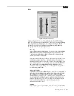
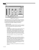
Metering
The gate meter shows the attenuation applied to the signal passing
through the gate at any given moment in time. When the signal is
below threshold and the gate is closed, the meter indicates negative
values (gain less than 1.0). When the signal is above threshold and
the gate is open, the meter indicates 0 dB (gain of 1.0). Meter values
are raw, no averaging or ballistics are applied.
Notes on Operation of the Gate
Bypass
Bypassing a gate causes the signal to pass through unaltered.
Computation of Average Level
There are two common methods of computing average signal
level; one is based upon RMS (Root Mean Square) calculations,
and the other is based upon Absolute Value calculations. Each
of these methods produces a slightly different value for signal
level, and the difference depends upon the characteristics of the
signal itself. The ISP-100 gate uses Absolute Value for its
computation of signal level, so the level reported by the gate
may differ slightly from the RMS value expected for a given
signal.
Keying from Other Channels
When the key channel input to a ISP-100 gate is selected to be
a channel other than its input, the gate controls must still be set.
The key channel selects only the channel’s data, not its gate
control settings. If multiple gates utilize the same channel as
their key sources, then all controls on all gates must still be
configured.
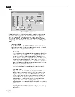
Metering
The meter located to the left of the component indicates the amount
of attenuation in dB.
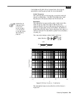
Attenuation and Threshold Controls
These controls can be adjusted three ways:
Using the Slider
Click on the indicator on the slider and while continuing to hold
down the mouse button, move the mouse up and down. The
numbers in the box below the slider will change. When the
desired level is reached, release the mouse button.
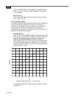
Using the Text Box
Click in the box. Using the Back Space and/or Delete keys
erases the current entry and enters the new level. Be sure to
press the Enter key after the entry is made. Clicking outside the
text box without pressing the Enter key will cause the setting to
return to the number that it was before a change was attempted.
Summary of Contents for Integrated Signal Processor ISP-100
Page 1: ...User s Manual ISP 100 INTEGRATED SIGNAL PROCESSOR...
Page 2: ...THIS PAGE LEFT BLANK INTENTIONALLY...
Page 24: ...2 10 10 July 1998 THIS PAGE LEFT BLANK INTENTIONALLY...
Page 32: ...3 8 10 July 1998 THIS PAGE LEFT BLANK INTENTIONALLY...
Page 48: ...5 6 10 July 1998 THIS PAGE LEFT BLANK INTENTIONALLY...
Page 126: ...A 4 10 July 1998 THIS PAGE LEFT BLANK INTENTIONALLY...
Page 128: ...B 2 10 July 1998 MONDOEQ QMS...
Page 129: ...B 3 Standard QuickMAPs 2X6CMBC QMS...
Page 130: ...B 4 10 July 1998 2X8COMB QMS...
Page 131: ...B 5 Standard QuickMAPs 3X6CMBC QMS...
Page 132: ...B 6 10 July 1998 2X8THRU QMS...
Page 133: ...B 7 Standard QuickMAPs 4CHAN QMS...
Page 134: ...B 8 10 July 1998 4X6CMBC QMS...
Page 135: ...B 9 Standard QuickMAPs 4X6THRU QMS...
Page 136: ...B 10 10 July 1998 3_2W QMS...
Page 137: ...B 11 Standard QuickMAPs 2WAYS QMS...
Page 138: ...B 12 10 July 1998 2_3WAY QMS...
Page 139: ...B 13 Standard QuickMAPs 2_2W_SUB QMS...
Page 140: ...B 14 10 July 1998 2_2W_FR QMS...
Page 141: ...B 15 Standard QuickMAPs 2_2W_2ST QMS...
Page 142: ...B 16 10 July 1998 4_2WAYS QMS...
Page 143: ...B 17 Standard QuickMAPs 4W_2FR QMS...
Page 144: ...B 18 10 July 1998 LCR QMS...
Page 145: ...B 19 Standard QuickMAPs MONO3W QMS...


