


8-37
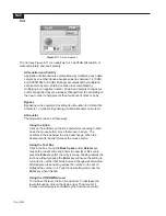
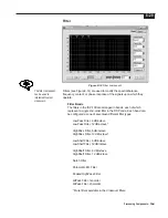
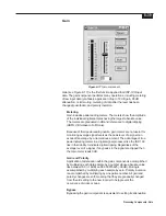
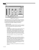
Processing Components - Filter
Alternatively, click and drag across the number in the box to
highlight the number in it. Type the new setting and press the
Enter key when finished.
Using the UP/DOWN Arrows
To increase the level, click on the up arrow. To decrease the
level attenuation, click on the down arrow. The amount of
increase or decrease is controlled by the fine/coarse control.
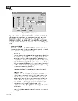
Using the Filter Tool
Right-click on the red dot on the active filter band. While holding
down the right-mouse button, move the mouse from side-to-side.
A display will appear indicating the bandwidth of the filter. When
the desired level is reached, release the right-mouse button.
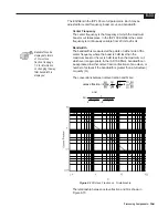
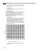
Using the Magnitude (Mag.) or Phase Control
This button allows the user to view the composite filter response in
either a magnitude vs. frequency or phase vs. frequency
environment. Clicking on the button will toggle the setting.
Using the Logarithmic (Log.) or Linear Control
This button allows the user to view the composite filter response in
either a logarithmic or linear environment. Clicking on the button will
toggle the setting.
Using the 24 dB, 40 dB, 120 dB Controls
These buttons allow the user to view the composite filter response in
three different dynamic ranges. Clicking on one of the buttons will set
the dynamic range.
Gain Trim
The Gain Trim can be used to shift response up or down. This is
especially useful with shelving filters. With shelving filters in a boost
situation, an amount of gain trim equal to the amount of boost should
be added. Gain trim does not need to be added in the case of a
shelving filter with cut. The Gain Trim can be adjusted two ways:
Using the Text Box
Click in the box. Using the Back Space and/or Delete keys
erases the current entry and enters the new level. Be sure to
press the Enter key after the entry is made. Clicking outside the
text box without pressing the Enter key will cause the setting to
return to the number that it was before a change was attempted.
Alternatively, click and drag across the number in the box to
highlight the number in it. Type the new setting and press the
Enter key when finished.
Using the Slider
Click on the indicator on the slider and while continuing to hold
down the mouse button, move the mouse side-to-side. The
numbers in the box next to the slider will change. When the
desired level is reached, release the mouse button.
Summary of Contents for Integrated Signal Processor ISP-100
Page 1: ...User s Manual ISP 100 INTEGRATED SIGNAL PROCESSOR...
Page 2: ...THIS PAGE LEFT BLANK INTENTIONALLY...
Page 24: ...2 10 10 July 1998 THIS PAGE LEFT BLANK INTENTIONALLY...
Page 32: ...3 8 10 July 1998 THIS PAGE LEFT BLANK INTENTIONALLY...
Page 48: ...5 6 10 July 1998 THIS PAGE LEFT BLANK INTENTIONALLY...
Page 126: ...A 4 10 July 1998 THIS PAGE LEFT BLANK INTENTIONALLY...
Page 128: ...B 2 10 July 1998 MONDOEQ QMS...
Page 129: ...B 3 Standard QuickMAPs 2X6CMBC QMS...
Page 130: ...B 4 10 July 1998 2X8COMB QMS...
Page 131: ...B 5 Standard QuickMAPs 3X6CMBC QMS...
Page 132: ...B 6 10 July 1998 2X8THRU QMS...
Page 133: ...B 7 Standard QuickMAPs 4CHAN QMS...
Page 134: ...B 8 10 July 1998 4X6CMBC QMS...
Page 135: ...B 9 Standard QuickMAPs 4X6THRU QMS...
Page 136: ...B 10 10 July 1998 3_2W QMS...
Page 137: ...B 11 Standard QuickMAPs 2WAYS QMS...
Page 138: ...B 12 10 July 1998 2_3WAY QMS...
Page 139: ...B 13 Standard QuickMAPs 2_2W_SUB QMS...
Page 140: ...B 14 10 July 1998 2_2W_FR QMS...
Page 141: ...B 15 Standard QuickMAPs 2_2W_2ST QMS...
Page 142: ...B 16 10 July 1998 4_2WAYS QMS...
Page 143: ...B 17 Standard QuickMAPs 4W_2FR QMS...
Page 144: ...B 18 10 July 1998 LCR QMS...
Page 145: ...B 19 Standard QuickMAPs MONO3W QMS...


