


Page 22
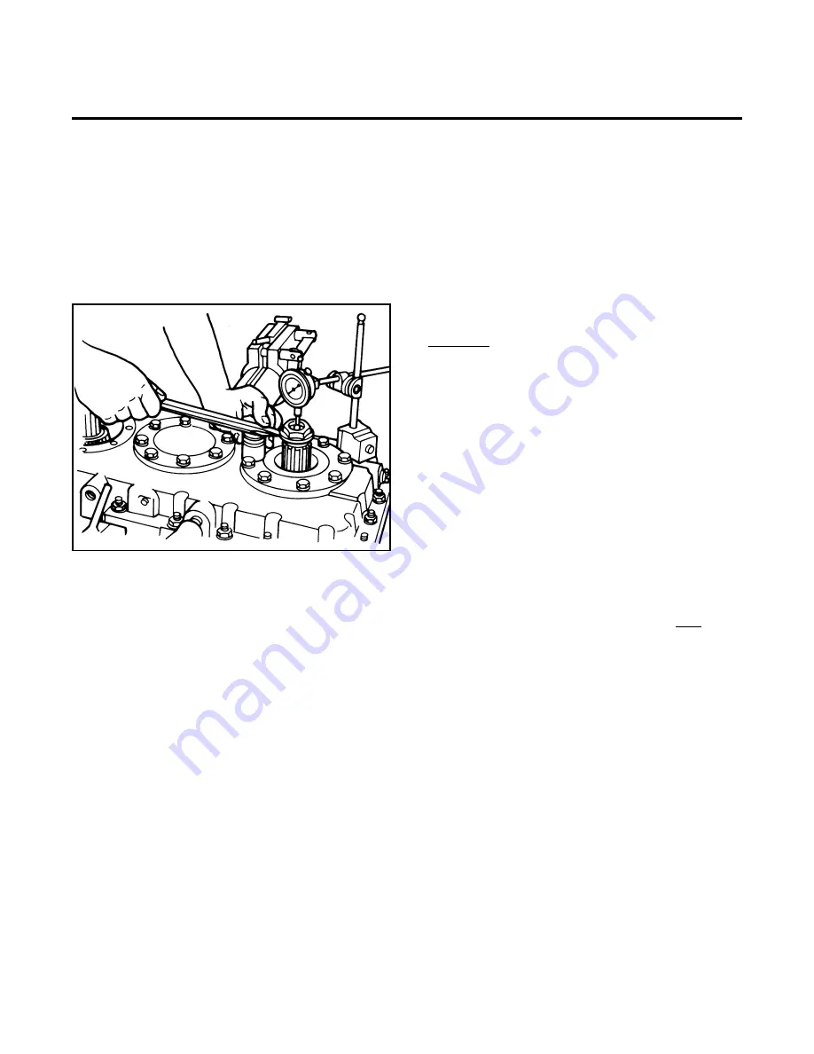
Check Bearing End Play
1. Install the yoke nut on the input shaft finger tight.
2. Set a small steel ball in the hole on the end of the
input shaft.
3. Check the end play with a dial indicator mounted
against the ball on the shaft. Figure 30.
NOTE:
It is critical that the bearings be completely seated
in both directions.
a. Seat the lower bearings by using the weight of
the gear plus a rotational and shaking motion.
Proper seating of the lower bearings is indicated
when movement of the dial indicator ceases. At
this point, zero the dial indicator.
b. Using the same rotational and shaking motion,
apply upward lift sufficient to seat the upper
bearing. Proper seating of the upper bearing is
indicated when the dial indicator ceases to
register upward movement.
NOTE:
The movement indicated by the dial indicator is the
preliminary end play that exists with the initial shim
stack.
c. Subtract the appropriate shim quantity and
thickness to close the end plays to within the
specified limits.
Example:
0.058 in. (1.473 mm) Preliminary end play
-0.003 in. (0.076 mm) Nominal desired end play
=0.055 in. (1.39 mm) Shim stack to be removed
4. The end play must be between 0.001 - 0.005 inch
(0.025 - 0.127 mm). Add shims to increase end play
or remove shims to decrease end play.
5. To check the end play of the rear output shaft, the
transfer case must be rotated so that the rear output
is on top.
6. Install the snap ring in the end of the output shaft.
7. Check the end play with a dial indicator mounted
against the end of the shaft. Take the reading while
you pry up against the snap ring and rotate the shaft
in both directions.
8. The end play must be between 0.001 - 0.005 inch
(0.025 - 0.127 mm). Add shims under the front output
bearing cage to increase end play or remove shims
to decrease end play.
Figure 30
Pro Gear and Transmission • 906 W. Gore St. Orlando, FL 32805 • 1 (877) 776-4600 / (407) 872-1901 • [email protected]